Method for protecting encapsulated sensor structures using stack packaging

Inactive Publication Date: 2008-10-02
ROBERT BOSCH GMBH
View PDF11 Cites 5 Cited by
  • Summary
  • Abstract
  • Description
  • Claims
  • Application Information

AI Technical Summary

Benefits of technology

[0006]It is believed that the exemplary embodiment and / or exemplary method may provide a higher stability for the micro-mechanical sensor structure at reduced cost. In particular, the exemplary embodiment and / or exemplary method may permit the encapsulated mechanical sensor structure to withstand the high molding pressures that may be encountered during fabrication, while at the same time reducing the overall package size and / or a required number of bond wires.
[0009]In a further exemplary embodiment and / or exemplary method, the thin protective membrane may be eliminated. In this case, a sealing bond ring arranged to surround the micro-mechanical sensor structure may protect the micro-mechanical element once the electronic integrated circuit chip is bonded to the sensor chip.
[0011]Yet another exemplary method of protecting a micro-mechanical sensor structure embedded in a micro-mechanical sensor chip includes configuring the protective membrane at a reduced thickness.
[0044]Yet another exemplary embodiment is directed to a micro-mechanical sensor device including a substrate, wherein a difference in dielectric coefficient for the RF chip as an upper chip and an additional space between the upper RF chip and the substrate provided by the use of the micro-mechanical sensor chip as an intermediate chip provides an improved RF performance.

Problems solved by technology

By doing so, the chip carrying the electronic circuitry may take over an additional mechanical task of supporting the thin membrane which would otherwise be too weak to withstand the pressures exerted on it during fabrication.

Method used


Image

  • Method for protecting encapsulated sensor structures using stack packaging
  • Method for protecting encapsulated sensor structures using stack packaging
  • Method for protecting encapsulated sensor structures using stack packaging

Examples


Embodiment Construction

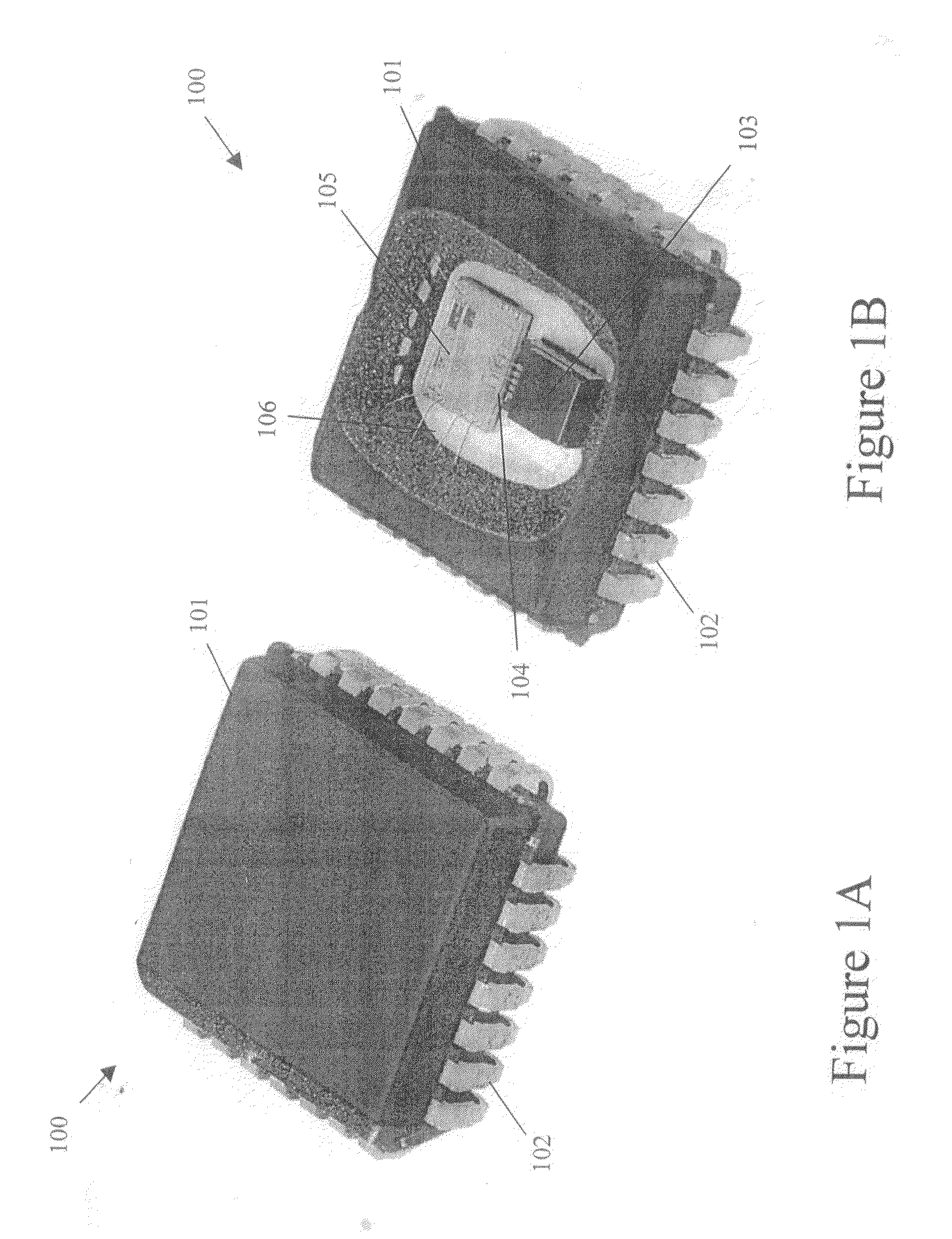
[0070]FIG. 1A shows an exterior view of a combined micro-mechanical sensor and electronic integrated circuit package 100 having a plastic molding 101 and outside electrical contacts 102. The plastic molding 101 provides a protective covering and mechanical support for the internal components of the combined micro-mechanical sensor and electronic integrated circuit package 100. The outside electrical contacts 102 provide an electrical connection to the internal components of the combined micro-mechanical sensor and electronic integrated circuit package 100.

[0071]FIG. 1B shows an interior view of the combined micro-mechanical sensor and electronic integrated circuit package 100 of FIG. 1A showing, in addition to the plastic molding 101 and outside electrical contacts 102, a micro-mechanical sensor chip 103, an electronic integrated circuit chip 105, a first series of bond wires 104, and a second series of bond wires 106. The micro-mechanical sensor chip 103 includes a micro-mechanical...


PUM

PropertyMeasurementUnit
thicknessaaaaaaaaaa
thicknessaaaaaaaaaa
lengthaaaaaaaaaa

Abstract

A method of protecting a micro-mechanical sensor structure embedded in a micro-mechanical sensor chip, in which the micro-mechanical sensor structure is fabricated with a protective membrane, the micro-mechanical sensor chip is arranged so that a surface of the protective membrane faces toward a second chip, and the micro-mechanical sensor chip is secured to the second chip.

Description

FIELD OF THE INVENTION[0001]The present invention relates to a method for protecting encapsulated micro-mechanical sensor structures.BACKGROUND INFORMATION[0002]Micro-mechanical sensor structures may be fragile and may be easily damaged and / or destroyed if they come in contact with foreign particles and / or liquids (including, for example, dirt and condensed humidity). Therefore, it may be desired to protect such structures early in the production process.[0003]Micro-mechanical sensor structures may be protected by applying an additional film of membrane layer during the production process to encapsulate the sensor structure and to shield its sensitive areas from undesired external contaminants, such as, for example, dust and dirt, or potentially harmful environmental conditions, such as, for example heat and humidity. The protective membrane layer, however, may be too thin to withstand the high pressures that may occur during the plastic molding of the micro-mechanical sensor struct...

Claims


Application Information

Patent Timeline
Patent Type & Authority Applications(United States)
IPC IPC(8): H01L23/02H01L21/50G01P15/08B81B3/00B81B7/00B81C1/00G01C19/56G01C19/5769G01P1/02G01P15/125G01P15/18H01L29/84
CPCB81B2207/095B81C1/00333B81C2203/0136G01P2015/0814G01P15/125G01P15/18G01P1/023H01L2224/16145H01L2224/48137H01L2224/48247H01L2224/48465H01L2224/49171H01L2924/181H01L2224/05554H01L2224/48091H01L2924/00012H01L2924/00014H01L2924/00
Inventor FUNK, KARSTEN
Owner ROBERT BOSCH GMBH
Why Eureka
Try Eureka