Tilting Vehicle

a technology of tilting vehicle and driver input, which is applied in the direction of interconnection system, steering parts, and resilient suspensions, etc., can solve the problems of affecting the performance of the vehicle, unable to achieve mechanical connection between the driver input and the front wheel [via a torque sensing spring in the sensor), and requiring inferior feedback methods

Inactive Publication Date: 2008-10-02
JAMES PHILLIP RONALD
View PDF7 Cites 161 Cited by
  • Summary
  • Abstract
  • Description
  • Claims
  • Application Information

AI Technical Summary

Benefits of technology

[0058]A desirable characteristic of the vehicle is the feedback to the driver via the control, due to the sensor reaction spring recording the vehicles natural tendency to always return to vertical. Observations indicate that this characteristic fundamentally derives from the fact that the front wheel / wheels run naturally at a steer angle which produces this “counter tilt force” This tilt force is a vehicle countersteer tilt force, and vehicle countersteer can be defined as “any steer angle that produces a tilt force”. Important consequences follow because when the vehicle is being forced to tilt into the corner, [the vehicle countersteer tilt force being balanced by the driver input / hydraulic assist tilt force], the weight on the outer wheels increases relative to the weight on the inner wheels. The vehicle is now gaining stability from its width of track, as well as its inclination. This allows the vehicle to corner at less tilt angle for any given speed and radius of corner. The vehicle is “under tilting”. The flow on effect is that the driver experiences a lateral loading which assists the judgement of his steer inputs. The term “load shedding” is used to describe this condition. The amount of load shedding can be easily varied throughout the vehicles full speed range by arranging the low speed variable force steer transmitter to operate outside its normal range under control of the ECU, and so various rates of tilt steer and load shedding can be applied to the vehicle as desired over the full range of vehicle speed. If, at higher speeds, no torque is applied to the wheel / wheels steer axis / axes by the variable force steer transmitter then most drivers will not be conscious of the effect, except in the way that it is represented in the self centering of the control. However if the “castoring element” is resiliently urged to steer more in the direction of the vehicle tilt by the variable force steer transmitter then the loading of the vehicle to return to vertical increases [as does the load shedding], and the steered vehicle path will be a tighter curved path relative to the vehicle tilt angle, and so the driver input angle on the control will be less to produce a given steered path radius at a given speed. And so the driver becomes more aware of the approaching vehicle limits and is better able to identify these limits, as is commonly learned in a conventional motorcar. The running steer angle position of the castoring element determines: 1] the loading on the vehicle to return to vertical, 2] The loading of the control to return to centre, 3] the loading of the outer wheels relative to the inner wheels, 4] the lateral loading on the driver and 5] The steered path radius relative to the driver input on the control. Those skilled in the art will be able to create the optimal vehicle “feel”.

Problems solved by technology

One disadvantage of this arrangement is that any mechanical connection between the driver input and the front wheel [via a torque sensing spring in the sensor], is detrimental to the performance of the vehicle due to a disturbance of the position of the wheel into a positive steer position before the application of the force to tilt the vehicle.
In this system no mechanical connection is possible between driver input and the vehicle tilting section.
Inferior feedback methods are required and there appears to be limited failsafe capacity suitable for a narrow vehicle.

Method used


Image

  • Tilting Vehicle
  • Tilting Vehicle
  • Tilting Vehicle

Examples


Embodiment Construction

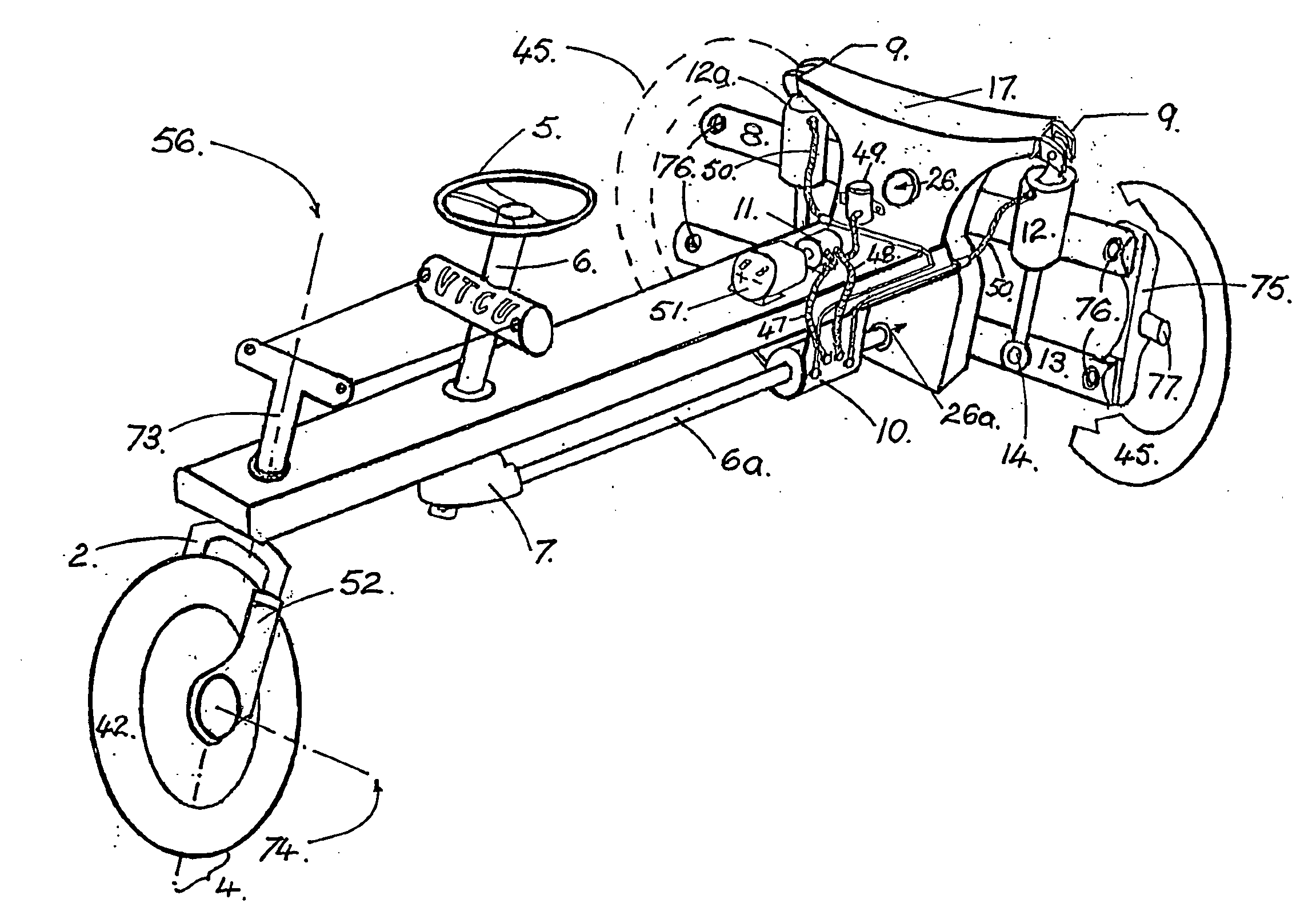
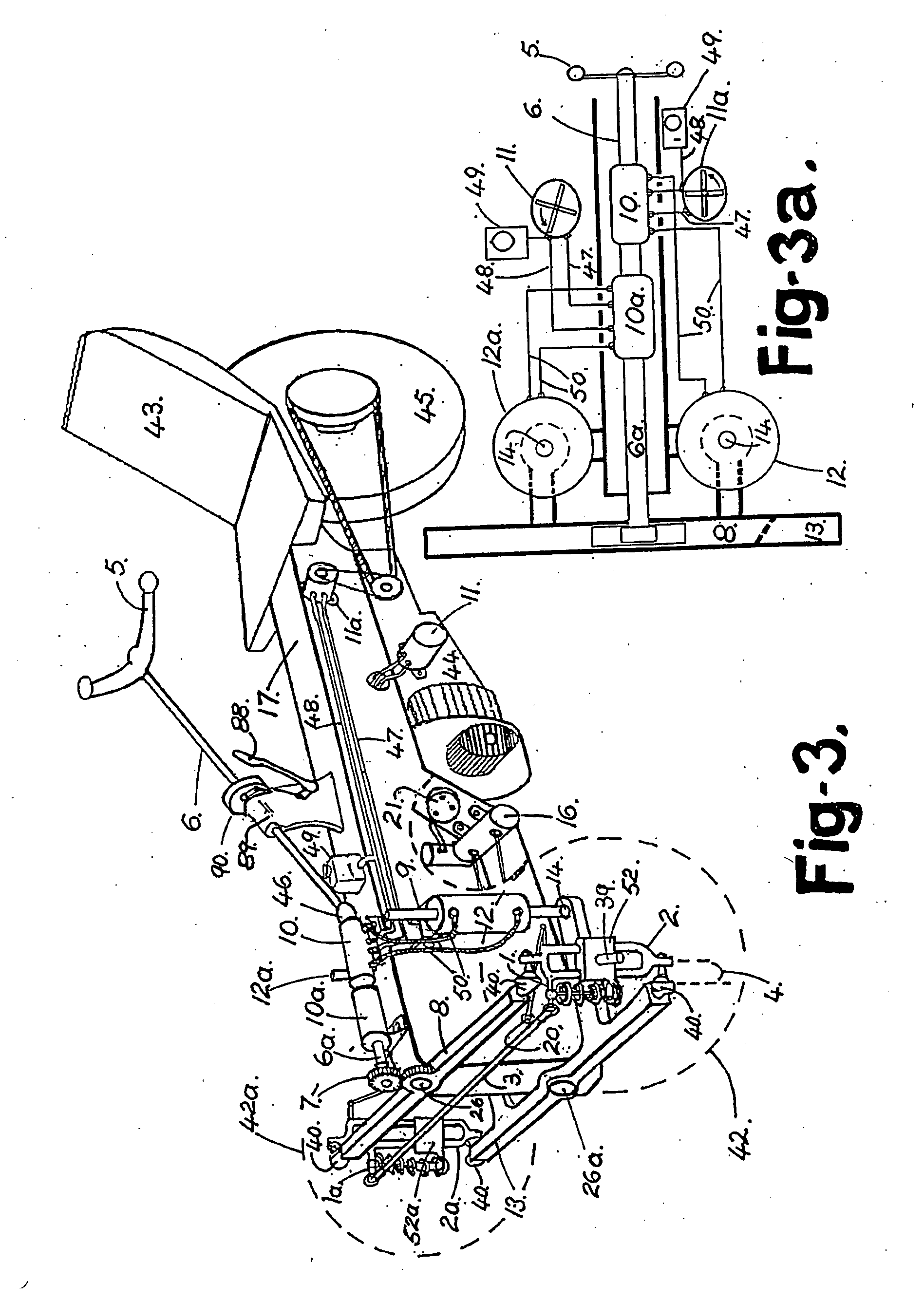
[0037]I will now describe the best way of performing my invention known to me when the vehicle has two front wheels and is operating above approximately 10 mph [16 kph]. The descriptions given include power assist tilt elements which are not absolutely necessary. The necessity depends on the vehicle mass, vehicle operating speed range, and the transmission ratio between control and tilt action. A vehicle with no power assist will be similar to the vehicle about to be described, with the power assist components removed. In FIG. [3] is shown a tilting vehicle of type [b] with a castoring element, in this case two front wheels [42,42a] [represented by dotted lines], that rotate on axles [39] [one visible] when the vehicle is under way. The axles attach to carriers [52,52a] sliding on parallel bars formed within the steer pivot suspension structures [2,2a], to allow suspension movement [as will be described in more detail later]. The wheels are arranged on either side of the centre of g...


PUM


Abstract

A tilting vehicle comprising at least one section (17) tiltable about the longitudinal axis of the vehicle, tilt registration means (20) recording variations in the tilt position of the tiltable section (17), a control element (5), tilt control means (12) connecting the control element (5) to the tilt section (17), at least three wheels (42, 42a, 45) including wheels (42, 42a) laterally spaced, a castoring element including at least one front wheel (42, 42a) able to tilt with the tiltable section (17) and dynamically directionally controllable due to the tilt and speed of the vehicle, a speed sensitive control signal transmitter (21), a variable force steer transmitter (16) connected to the castoring element, the tilt registration means (20) and to the speed sensitive control signal transmitter (21), the variable force steer transmitter (16) being able to exert a directing moment and / or positioning moment on the castoring element, that directs and / or positions the castoring element according to the tilt registration means (20) and the force exerted by the variable force steer transmitter (16), which is varied by control signals from the speed sensitive control signal transmitter (21).

Description

FIELD OF THE INVENTION[0001]This invention relates to the field of narrow tilting vehicles that have overall dimensions similar to a normal motorcycle, and which obtain their stability by inclination of the vehicle / occupant mass to offset the effects of centrifugal force when cornering. This invention sets out a simple system of control to replace the complex control used on a conventional motorcycle. This will enable the widespread use of narrow tilting vehicles by operators with common skills. The advantage of such a vehicle is the reduction of the energy required to transport the occupants, and the reduction of the space required to park the vehicle, combined with an incentive for the use of the vehicle due to its simple control and inherently satisfying dynamics. In order to achieve this ability the tilting vehicle described in this invention uses what is termed “simple steer”. The full control of the vehicle is achieved by the use of a single control, a displacement of the cont...

Claims


Application Information

Patent Timeline
Patent Type & Authority Applications(United States)
IPC IPC(8): B62D9/02B62K5/08
CPCB62D9/02B62K5/027B62K5/05B62K5/08B62K5/10
Inventor JAMES, PHILLIP RONALD
Owner JAMES PHILLIP RONALD
Why Eureka
Try Eureka