Compact Planar Antenna For Single and Multiple Polarization Configurations

a planar antenna and configuration technology, applied in the direction of slot antennas, antenna details, antennas, etc., can solve the problems of large height of the antenna, low efficiency, and inability to meet the requirements of the operation of the other antenna or circuit in the vicinity

Active Publication Date: 2008-10-02
CAES SYST LLC
View PDF17 Cites 30 Cited by
  • Summary
  • Abstract
  • Description
  • Claims
  • Application Information

AI Technical Summary

Problems solved by technology

Furthermore, it likely would couple to and interfere with the operation of other antennas or circuits in the vicinity.
While this type of planar antenna has many good qualities, it also suffers from some significant disadvantages.
Most notably, the requirement for a one-quarter wavelength metallic cavity causes the antenna to have a significant height.
This might render the design unsuitably tall for many applications, including automotive applications, where a low profile is important.
However, while proximity coupled or L-probe coupled antennas can be made thinner, they also have several significant drawbacks.
First, they suffer from poor cross polarization.
Furthermore, in the case of dual polarization antennas, the isolation between the two polarizations is very poor.

Method used


Image

  • Compact Planar Antenna For Single and Multiple Polarization Configurations
  • Compact Planar Antenna For Single and Multiple Polarization Configurations
  • Compact Planar Antenna For Single and Multiple Polarization Configurations

Examples


Embodiment Construction

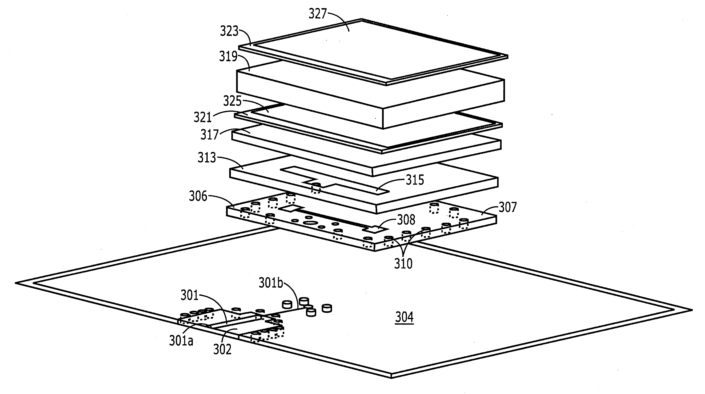
[0020]FIGS. 3A-3E are drawings of a first exemplary embodiment of the present invention. FIG. 3A is a cross sectional side view, FIG. 3B is a perspective view of some of the layers, FIG. 3C is a perspective view showing additional layers, FIG. 3D is a perspective view of the complete antenna showing all layers, and FIG. 3E is an exploded view of all of the layers of the antenna. With reference to FIGS. 3A and 3B first, a feed line in the form of a strip line 301 is provided. Alternatively, the antenna could be fed from the bottom by a coaxial input. The strip line 301 is sandwiched between two ground planes, namely, a lower ground plane 303 and an upper ground plane 305. More particularly, the strip line 301 is formed on the surface of a suitable thin dielectric substrate such as a 5 mil thick flex board 302 (or 304). The term flex board is used generically in the relevant industries to refer to a very thin (usually 1 to 5 mils thick) flexible dielectric board. One example is Pyralu...


PUM


Abstract

A planar antenna comprising a signal path for receiving or transmitting a signal, a conductive layer having a slot formed therein positioned to electromagnetically couple with the signal path, a conductive plate parallel to and overlying the slot and spaced therefrom by a dielectric layer, the conductive plate being electrically in contact with the signal path, and one or more patches parallel to and above the conductive plate.

Description

FIELD THE INVENTION[0001]The invention pertains to antenna configurations. More particularly, the invention pertains to planar antennas with single or multiple polarizations.BACKGROUND OF THE INVENTION[0002]Slot or aperture-coupled planar patch antenna configurations are known for providing antennas having large frequency bandwidth. FIGS. 1A and 1B are an exploded perspective view and a cross-sectional elevation view of an exemplary slot-coupled patch antenna 100 of the prior art. The antenna comprises five major components, namely, a microstrip transmission feed line 103, a ground plane 105, a slot 104 in the ground plane, one or more radiating patches 107, 109 and a metallic cavity 117 (shown only in FIG. 1B). With reference to the Figures, a first substrate 101 has a transmission line 103 formed on one surface thereof and a ground plane 105 formed on the opposing surface. The substrate 101 may be any suitable dielectric substrate on which copper can be deposited or otherwise form...

Claims


Application Information

Patent Timeline
Patent Type & Authority Applications(United States)
IPC IPC(8): H01Q13/10
CPCH01Q9/0457
Inventor CHANNABASAPPA, ESWARAPPA
Owner CAES SYST LLC
Why Eureka
Try Eureka