Extremely miniaturized FM frequency band antenna
a frequency band antenna, ultra-miniaturized technology, applied in the direction of antenna details, non-resonant long antennas, antennas, etc., can solve the problem that users cannot listen to fm broadcast programs
- Summary
- Abstract
- Description
- Claims
- Application Information
AI Technical Summary
Problems solved by technology
Method used
Image

Examples
first embodiment
[0024]With reference to FIG. 4, it is a schematic view showing the present invention. As shown in this figure, when the FM antenna structure is completely manufactured, the first contact 121 of the micro strip line 12 is electrically connected to a lead 3, and the other end of the lead 3 is electrically connected to a main circuit board 5 of the mobile device. The user only needs to turn on the power supply of the mobile device (such as a mobile phone, mp3, recording pen or the like) and switches to the FM reception function or presses the FM button directly, thereby receiving the FM broadcast programs.
second embodiment
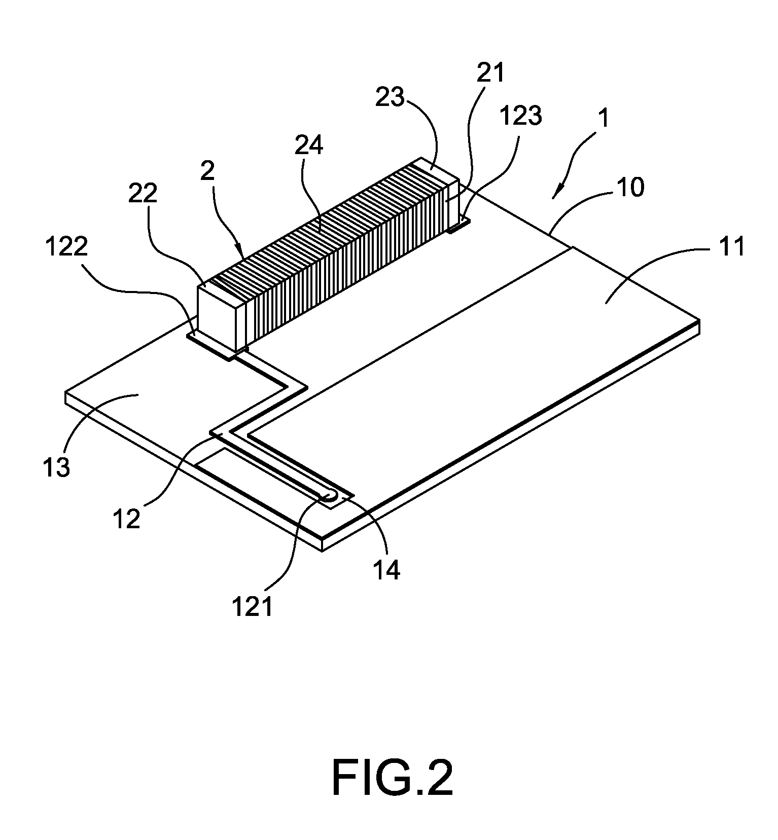
[0025]With reference to FIG. 5, it is a schematic view showing the present invention. As shown in this figure, the substrate 1 of the FM antenna structure of the present invention and the main circuit board 5 of the mobile device 4 can be the same circuit board. During the manufacturing of the main circuit board 5 of the mobile device 3, the grounding metallic surface 11 of the substrate 1, the first contact 121, the second contact 122 and the third contact 123 of the micro strip line 12 can be directly made on the main circuit board 5. The antenna unit 2 is electrically connected to the second and third contacts 122, 123 of the main circuit board 5 directly. The back or front surface of the main circuit board 5 is formed with a metallic lead 6 for electrically connecting with the first contact 121. After the antenna unit 2 receives the signals, the metallic lead 6 transmits the signals to the circuitry of the main circuit board 5 via the micro strip line 12 and the first contact 12...
third embodiment
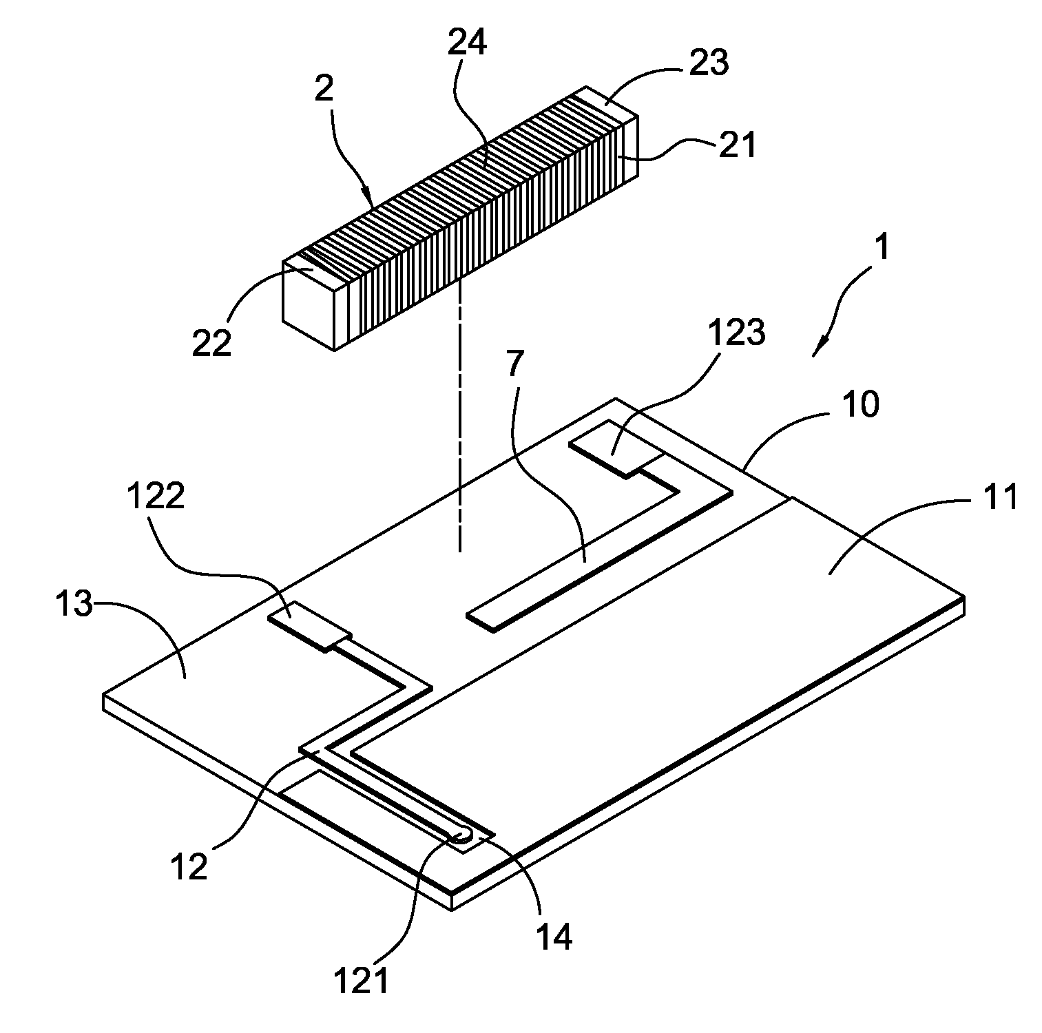
[0026]With reference to FIG. 6, it is a schematic view showing the present invention. As shown in this figure, in the FM antenna structure of the present invention, a metallic line 7 extends from the distal end of the third contact 123 of the substrate 1 according to the environmental conditions, thereby increasing the radiation gain. Furthermore, the width or length of the metallic line 7 can be adjusted to obtain an optimal central resonant frequency of the antenna via fine adjustment.
PUM
 Abstract
Description
Claims
Application Information
 - R&D
- Intellectual Property
- Life Sciences
- Materials
- Tech Scout
- Unparalleled Data Quality
- Higher Quality Content
- 60% Fewer Hallucinations
Browse by: Latest US Patents, China's latest patents, Technical Efficacy Thesaurus, Application Domain, Technology Topic, Popular Technical Reports.
© 2025 PatSnap. All rights reserved.Legal|Privacy policy|Modern Slavery Act Transparency Statement|Sitemap|About US| Contact US: help@patsnap.com