Droplet ejection device

a technology of droplet and ejection device, which is applied in the direction of printing, other printing apparatus, etc., can solve the problems of reducing the size of ink droplets, deteriorating recording image quality, and inability to eject ink that ink is hardly ejected, so as to reduce wasteful recovery operation, save liquid consumption and power consumption, and enhance economy

Inactive Publication Date: 2008-10-02
BROTHER KOGYO KK
View PDF10 Cites 11 Cited by
  • Summary
  • Abstract
  • Description
  • Claims
  • Application Information

AI Technical Summary

Benefits of technology

[0009]Accordingly, one of advantages of the present invention is capable of providing a droplet ejection device enhancing economy.
[0010]Another one of the advantages of the present invention is capable of setting a condition for recovery control based on a volume of a droplet ejected first under a subsequent ejection control.
[0011]Yet another one of the advantages of the present invention is capable of reducing wasteful recovery operation to save liquid consumption and power consumption.

Problems solved by technology

Such a recording head that performs recording by ejecting ink from nozzles suffers from a problem in that a solvent (water or the like) in ink is gradually dried to increase viscosity of ink in nozzles that have few chance to perform ejection or in nozzles when recording operation is suspended.
As a result, there arises failures such as a decrease in the size of ink droplets or an ink ejection failure that ink is hardly ejected.
These failures deteriorate recording image quality.
However, the recovery operation has hitherto been performed indiscriminately regardless of specifics of ejecting operation.
On the other hand, when the volume of droplets to be ejected is small, an increase in the viscosity of the liquid greatly affects ejection.
Therefore, wasteful consumption of a liquid and wasteful consumption of power associated with drying prevention driving have hitherto been performed, which impairs economy.

Method used


Image

  • Droplet ejection device
  • Droplet ejection device
  • Droplet ejection device

Examples


first example

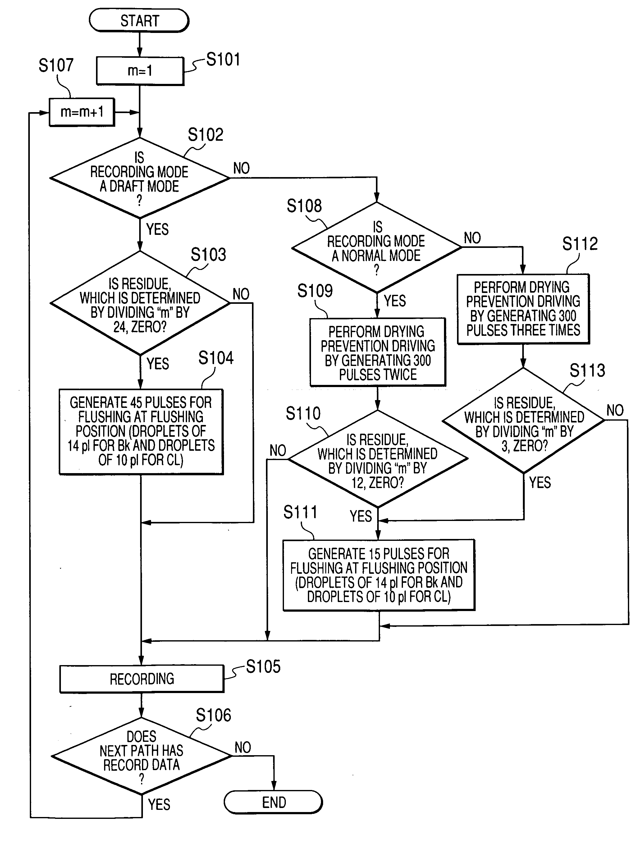
[0042]In the present example, as shown in Table 1, the draft mode, a normal mode, and a photographic mode are provided as recording modes. The draft mode is one for recording image data by sampling every other pixel from the image data in the sheet conveyance direction and by using only droplets having a large volume (hereinafter called “large droplets”) in order to speedily perform recording irrespective of gradation or the like. The normal mode is one for recording all pieces of image data by using the large droplets and droplets which are small in volume than the large droplets (hereinafter called “small droplets”) without sampling the data as in the draft mode. The photographic mode is one for performing recording operation by using large droplets and small droplets which are small in volume than the large droplets and the small droplets used in the normal mode, respectively. In Table 1, symbol “−” designates nonuse of ink, thus no volume of a droplet. Designation “LF” denotes a...

second example

[0053]The second example is identical with the first example in terms of the recording modes and the volumes of droplets used in the respective recording modes. Moreover, the second example is also identical with the first example in terms of the drive pulse signal used for drying prevention driving and the drive pulse signal used for flushing. When a droplet to be first ejected in accordance with record data signal in ink droplet ejection control subsequent to each recovery operation is of small size, drying prevention driving and flushing are performed under conditions provided in Tables 2 and 3. When the droplet is of large size, drying prevention driving and flushing are performed under conditions provided in Tables 4 and 5. Specifically, when the droplets are large, the ink is resistant to drying. Therefore, the number of pulses generated for drying prevention driving is decreased, and the number of droplets ejected for flushing and the size of a droplet used for flushing, are ...

third example

[0058]In the control for drying prevention driving in the first and second examples, the drive pulse signal for the small droplet and the drive pulse signal for the large droplet are set to be the same pulse width of 0.6 AL, and the number of pulses is changed. Instead, as shown in FIG. 7A, a pulse width can be changed with the number of pulses unchanged (the third example is identical with the second example except processing pertaining to steps S11′ and S18′). Specifically, when the droplet is of small size, a pulse width of 0.6 AL shown in FIG. 7B is used (steps S10 and S17). When the droplet is of large size, a pulse width of 0.25 AL shown in FIG. 7C is used (steps S11′ and S18′). Namely, the third example is identical with the first example in that drying prevention driving is performed in the normal mode by generating 300 pulses twice at an interval of 100 sec and in that drying prevention driving is performed in the photographic mode by generating 300 pulses three times at an...


PUM


Abstract

A droplet ejection device includes: an ejection head having an actuator and a nozzle; an interface configured to receive data; and a controller configured to (a) execute, based on the received data, ejection control in which liquid droplets having respective different volumes are selectively ejected from the nozzle to a medium by driving the actuator and (b) execute recovery control in which ejection performance of the recording head is recovered by driving the actuator. The controller is configured to (c) determine, based on the received data, a volume of a droplet to be first ejected from the nozzle under the ejection control subsequent to the recovery control, and (d) set, based on the determined volume, a condition for driving the actuator to execute the recovery control.

Description

CROSS REFERENCE TO RELATED APPLICATION[0001]The present disclosure relates to the subject matter contained in Japanese patent application No. 2007-090265 filed on Mar. 30, 2007, which is expressly incorporated herein by reference in its entirety.TECHNICAL FIELD[0002]The present invention relates to a droplet ejection device capable of ejecting droplets, and more particularly to control for preventing an ejection failure, which would otherwise be caused as a result of drying of liquid in the vicinity of nozzles.BACKGROUND ART[0003]An ink jet printer is one of embodiments of a droplet ejection device. The inkjet printer is configured such that a drive pulse is applied to a piezoelectric actuator to change the volume of pressure chambers filled with ink and communicating with nozzles of a recording head when the recording head reciprocally scans a record area of a recording medium. This way, the ink jet printer ejects ink droplets from the nozzles of the recording head to the recording...

Claims


Application Information

Patent Timeline
Patent Type & Authority Applications(United States)
IPC IPC(8): B41J29/38
CPCB41J2/04551B41J2/04581B41J2/04593B41J2/04595B41J2/04596B41J2/16526
Inventor TAKAHASHI, YOSHIKAZU
Owner BROTHER KOGYO KK
Why Eureka
Try Eureka