Headlamp for Vehicles

a headlamp and vehicle technology, applied in the direction of vehicle components, signalling/lighting devices, lighting and heating apparatus, etc., can solve the problem of limited variability in generating different light distributions, and achieve the effect of reducing illumination

Inactive Publication Date: 2008-10-02
HELLA KG HUECK & CO
View PDF3 Cites 73 Cited by
  • Summary
  • Abstract
  • Description
  • Claims
  • Application Information

AI Technical Summary

Benefits of technology

[0011]The particular advantage of the invention is that only a limited number of grouped LED light sources is necessary to produce a large number of different light distributions. An inventive headlamp incorporates different optical units with different sets of projection characteristics which are allocated to the groups of LED light sources such that different light distributions can be produced depending on whether one or several LED light sources of the first group of LED light sources and the second group of LED light sources or further groups are driven. For example, combining or overlapping groups of LED light sources allows the generation of light distributions for low beam or high beam or bend lighting or marker light functions or light distribution for motorway driving. The invention utilizes the fact that different projection characteristics will convert the same beam of light rays emitted by each of the LED light sources into differently sized spots of light in the road space.
[0012]One practical use is that this feature allows a leveling of some parts of a light distribution in conformity with statutory regulations. Or some very limited parts of the light distribution could be highlighted or blanked out.
[0013]In a further development of the invention, a first group of LED light sources and a first optical unit generate a first partial light distribution and a second group of LED light sources and a second optical unit generate a second partial light distribution, wherein the first partial light distribution and the second partial light distribution illuminate different road spaces. Making the two partial light distributions overlap resu

Problems solved by technology

However, since all LED light sources share but a single converging lens,

Method used


Image

  • Headlamp for Vehicles
  • Headlamp for Vehicles
  • Headlamp for Vehicles

Examples


Embodiment Construction

[0028]The following description of the preferred embodiment(s) is merely exemplary in nature and is in no way intended to limit the invention, its application, or uses.

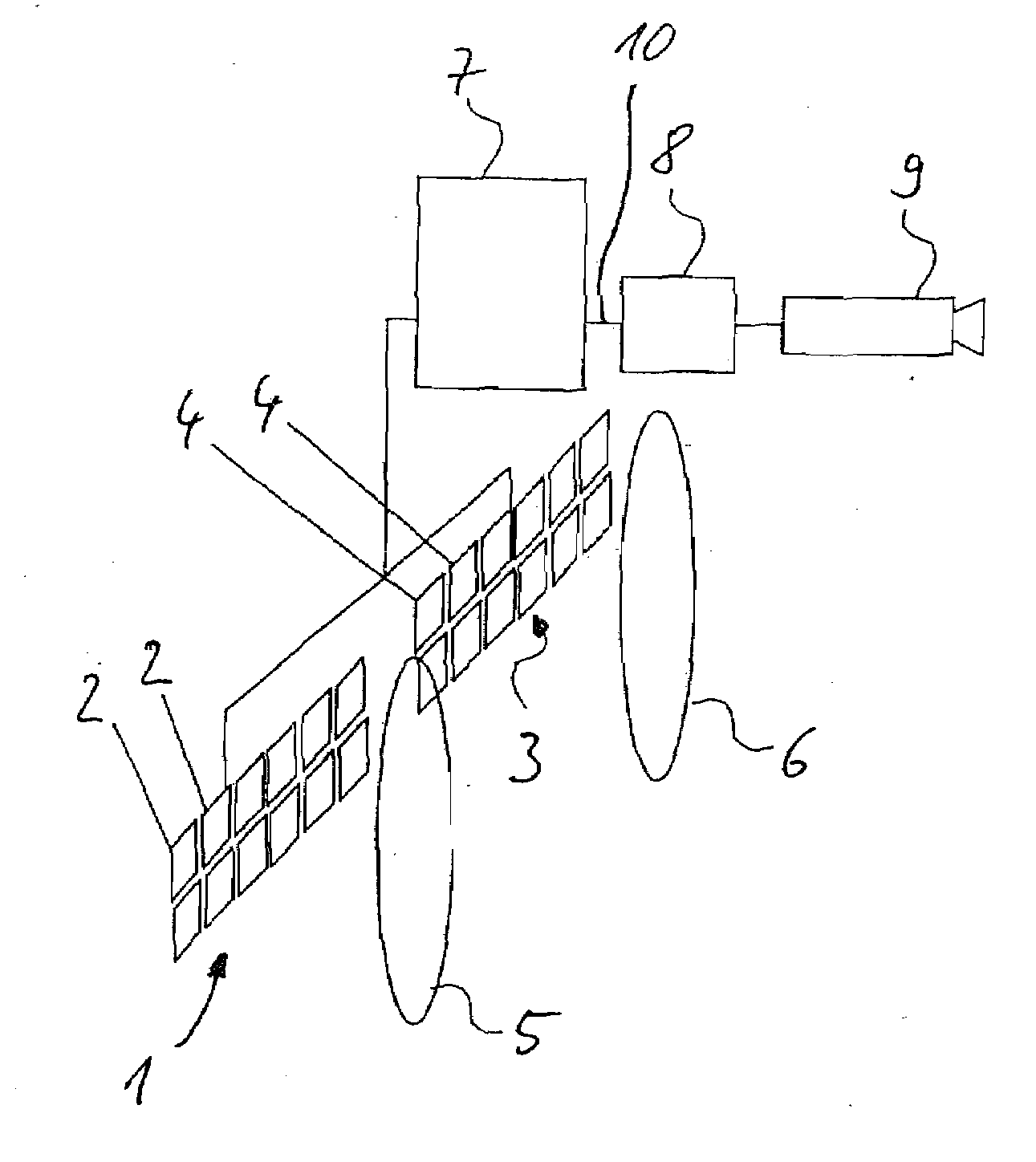
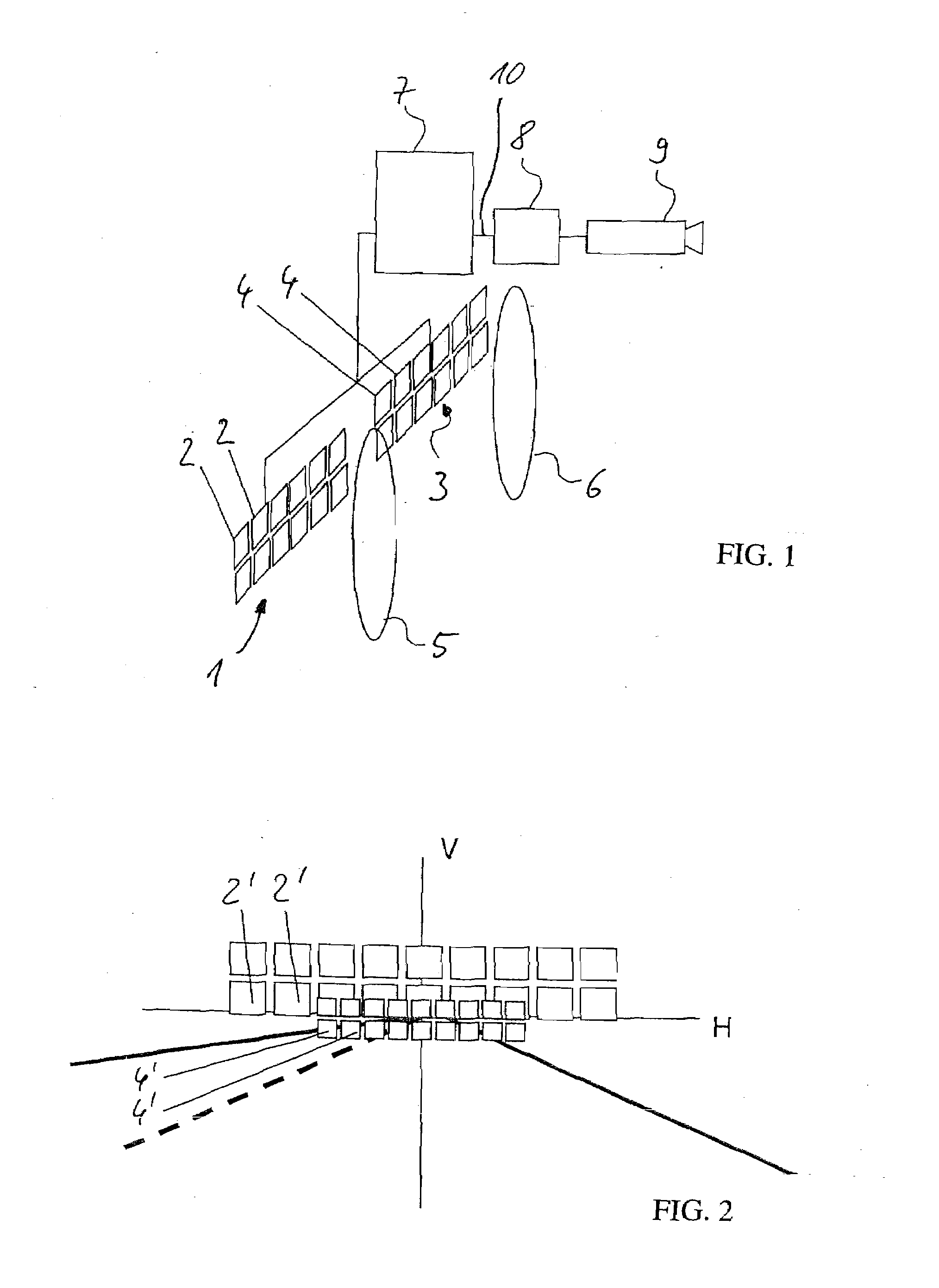
[0029]FIG. 1 is a schematic view of an inventive headlamp for vehicles. The headlamp consists of optical components comprising a first group 1 of LED light sources 2 and a second group 3 of a plurality of LED light sources 4. The LED light sources are designed as LED chips (light-emitting semiconductor diodes) which are arranged into groups—i.e. a first group 1 and a second group 3—to make up a light-emitting surface on a shared substrate but each in its own LED chip array.

[0030]The first group 1 of LED light sources 2 is allocated a first optical unit 5 and the second group 3 of LED light sources 4 is allocated a second optical unit 6, each of which said optical units are located before the group 1 and the second group 3 of LED light sources. Every LED light source 2, 4 of the first group 1 and the second group 3 is ...


PUM


Abstract

The present invention relates to a headlamp for vehicles with a plurality of LED light sources combined into a single light-emitting surface, where an optical unit is allocated to at least one LED light source to generate some of a specified light distribution, where one or several LED light sources can be turned on or off such that the light distribution can be modified, where a first optical unit with first projection characteristics is placed before a first group of LED light sources and a second optical unit with second projection characteristics is placed before a second group of LED light sources such that a number of differently sized light spots can be generated in the traffic space by optionally turning on or off or dimming the LED light sources of the first group of LED light sources or the second group of LED light sources.

Description

CROSS-REFERENCE TO RELATED APPLICATIONS[0001]This application claims priority to international application PCT / EP2006 / 065665 filed on Aug. 25, 2006 which claims priority to German application DE 10 2005 041 234.3 filed Aug. 31, 2005.STATEMENT REGARDING FEDERALLY SPONSORED RESEARCH[0002]Not Applicable.APPENDIX[0003]Not Applicable.BACKGROUND OF THE INVENTION[0004]1. Field of the Invention[0005]The present invention relates to a headlamp for vehicles comprising a plurality of LED light sources that share the same light-emitting surface such that an optical unit is allocated to at least one LED light source to generate some of a predefined light distribution, and such that groups of one or several LED light sources can be turned on or off in a way that will modify the light distribution.[0006]2. Related Art[0007]DE 100 09 782 A1 describes a headlamp for vehicles with a plurality of LED light sources which are arranged in the shape of a matrix. An optical unit designed as a converging le...

Claims


Application Information

Patent Timeline
IPC IPC(8): B60Q1/00
CPCB60Q1/085B60Q1/143B60Q2300/056B60Q2300/122B60Q2300/334B60Q2300/42B60Q2300/45F21S48/1154F21S48/1258F21S48/1747F21S41/143F21S41/255F21S41/663F21S41/153B60Q2300/312
Inventor WULLER, MARTINDECIUS, NIKOLAUSEICHHORN, KARSTENGOTZ, MIRCOHAGEDORN, SUSANNELUDER, CHRISTIAN
Owner HELLA KG HUECK & CO
Why Eureka
Try Eureka