
Droplet detection system

a detection system and droplet technology, applied in the field of image analysis, can solve the problems of system inability to detect or issue any report, large amount of fluid can be unnecessarily wasted, and the nozzles used for dispense operation are generally very small, so as to avoid material waste or equipment malfunction, and accurate high throughput screening

Inactive Publication Date: 2008-10-02
KALYPSYS INC +1
View PDF5 Cites 8 Cited by
  • Summary
  • Abstract
  • Description
  • Claims
  • Application Information

AI Technical Summary

Benefits of technology

The present invention is a system for detecting droplets in a high throughput screening process. It includes a plate with wells and a dispenser for dispensing fluid into the wells. An illuminating sensor extracts image features from the wells and well walls, and a controller analyzes these features to determine if the fluid is present on the wells and well walls. This system can detect clogging or blockages of the dispenser, which can prevent material waste or equipment malfunctions. The invention provides a more accurate and efficient way to screen and avoid issues during the dispensing process.

Problems solved by technology

Accordingly, if an undesirable condition or malfunction occurs (e.g. the dispenser clogs), the system cannot detect or issue any report of such condition until perhaps the final read step.
For a large screening involving hundreds or thousands of plates, a tremendous amount of fluid can be unnecessarily wasted.
Dispense nozzles used for the dispensing operation are generally very small, and therefore can easily be blocked or clogged during the dispensing operation.
Likewise, if one or more of the dispensing nozzles are partially blocked, then such blockage may cause the dispensing stream to be off target, i.e., the droplets may be dispensed onto the top surfaces of the plate rather than into the corresponding wells.
Although various vision or image systems have been implemented for specific applications, such as vial counting, inspecting pipettes, or locating pamphlets, none of such systems has been integrated in a detection system to determine the operation condition of a cell or reagent dispenser.

Method used


Image

  • Droplet detection system
  • Droplet detection system
  • Droplet detection system

Examples


Embodiment Construction

[0019]While specific exemplary examples, environments and embodiments are discussed below, it should be understood that this is done for illustration purposes only. A person skilled in the relevant art will recognize that other components and configurations can be used without parting from the spirit and scope of the invention. In fact, after reading the following description, it will become apparent to a person skilled in the relevant art how to implement the invention in alternative examples, environments and embodiments.

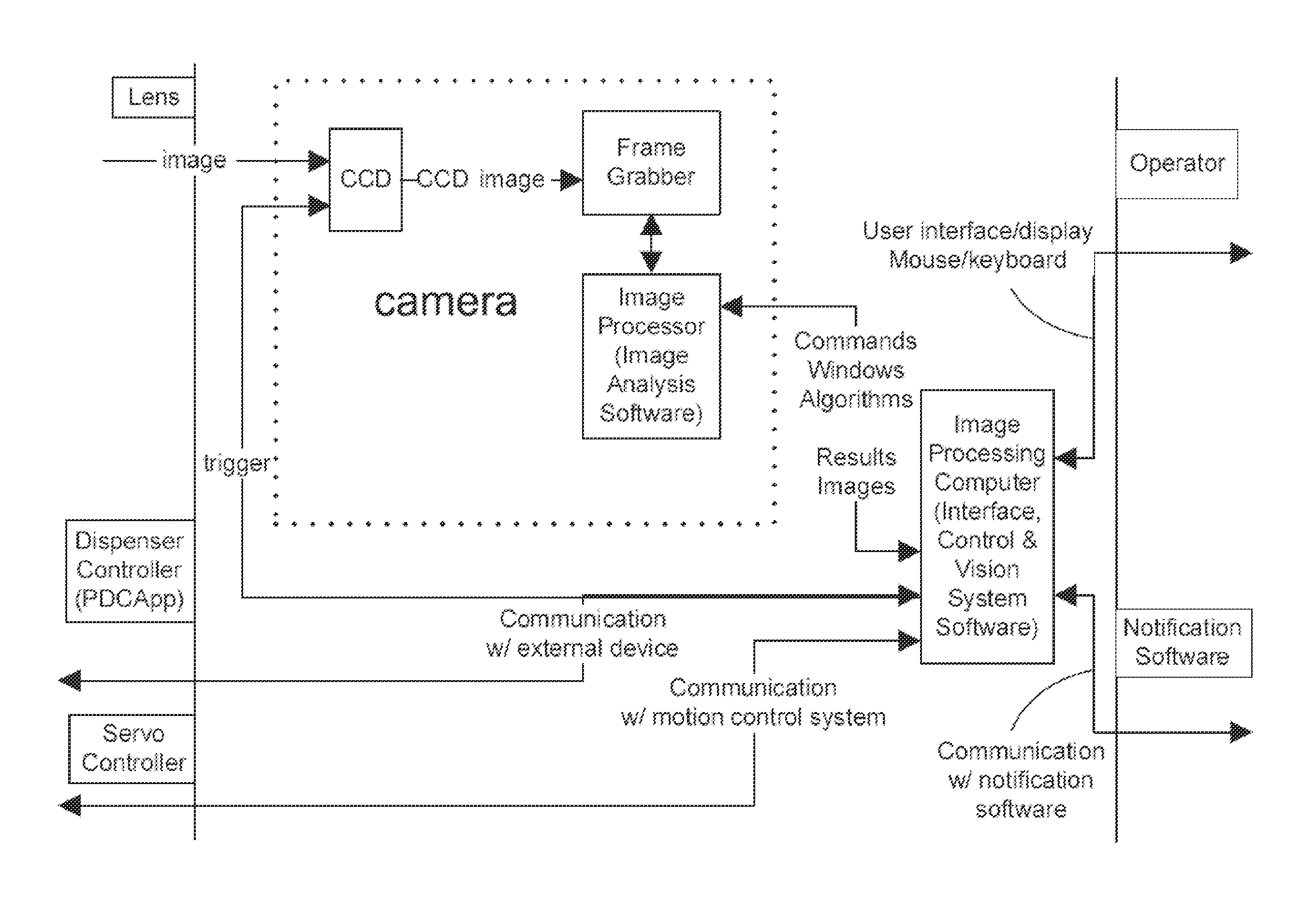
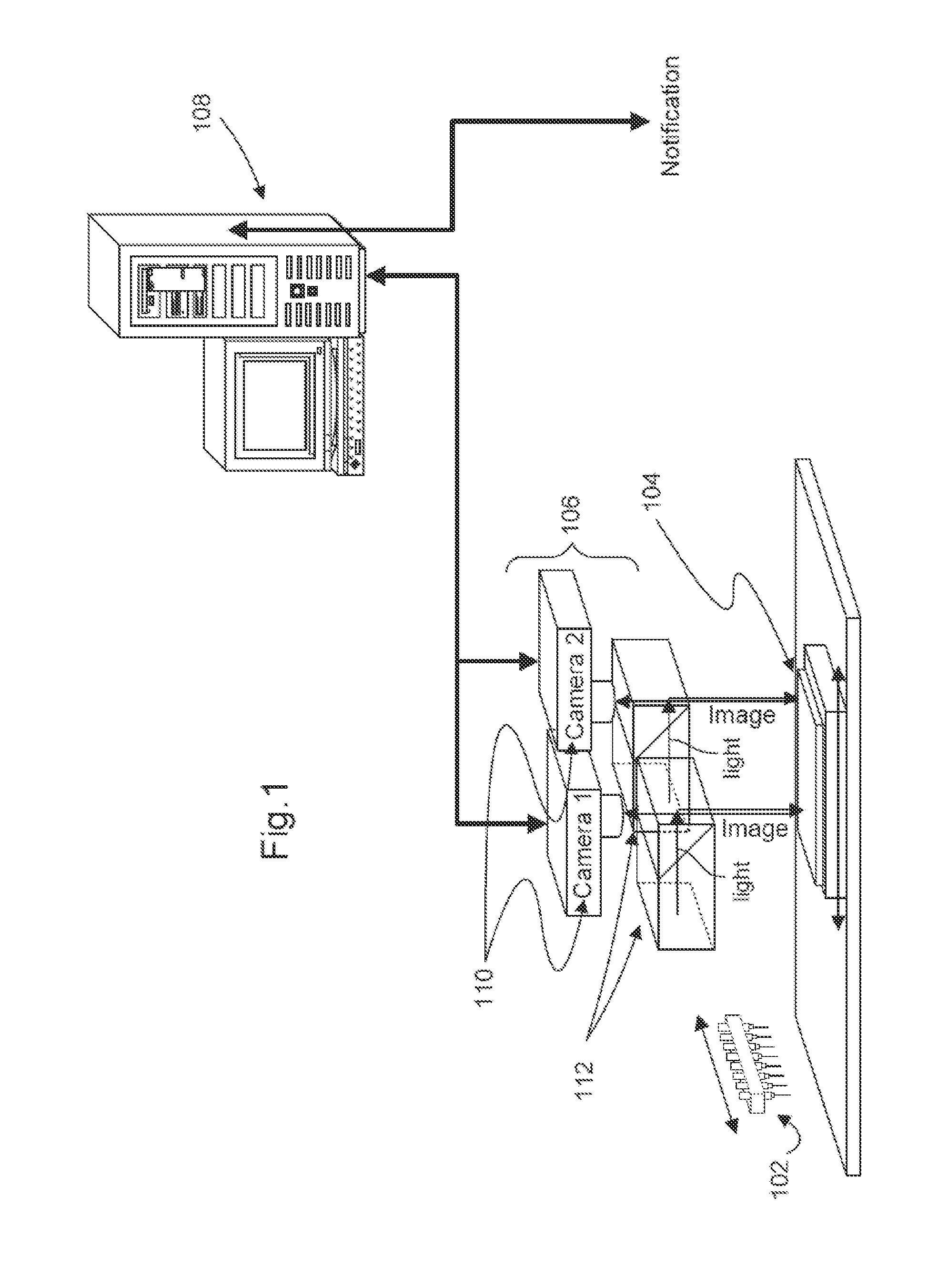
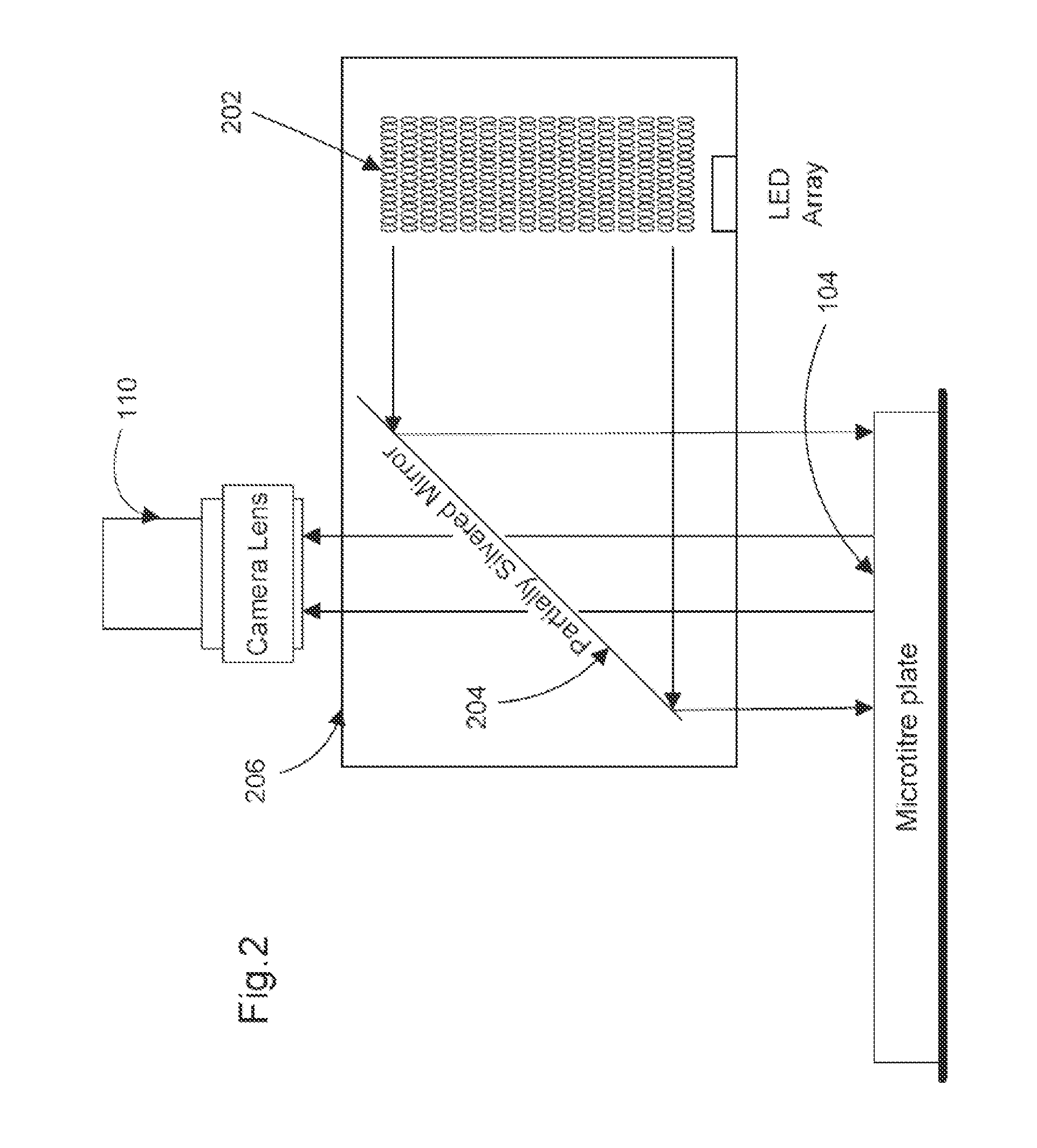
[0020]FIG. 1 shows a droplet detection system for monitoring a dispensing operation in a high throughput screening typical according to an exemplary embodiment of the invention. An 8-channel dispenser with y-axis motion 102 for dispensing fluid, reagents, or sample compounds into discrete wells of a microtitre plate 104, which can be, for instance, a 1536-well assay plate having 32 rows and 48 columns of wells that are evenly spaced apart by well walls therebetwee...


PUM

PropertyMeasurementUnit
light intensityaaaaaaaaaa
structureaaaaaaaaaa
dimensionsaaaaaaaaaa

Abstract

A system for a droplet detection device to monitor the dispensing operation in an ultra high throughput (uHTS) system. The system includes a microtitre plate with a defined number of wells and well walls, a dispenser for dispensing fluids into the wells, an illuminating sensor to extract image features from the wells and well walls, and a controller for analyzing the extracted image features to determine the presence or absence of the dispensing fluid on the wells and well walls.

Description

[0001]This application claims the benefit of priority of U.S. provisional application No. 60 / 849,141, filed Oct. 3, 2006, the disclosure of which is hereby incorporated by reference as if written herein in its entirety.BACKGROUND OF THE INVENTION[0002]1. Field of the Invention[0003]The present invention relates generally to image analysis in High Throughput Screening (HTS) or Ultra High Throughput Screening (uHTS) system. More specifically, the present invention is directed to a droplet detection system for monitoring the dispensing operation in the HTS or uHTS system.[0004]2. Related Art[0005]Typical procedure for HTS and uHTS systems includes dispensing one or more fluids (e.g., cells, reagents, media, and buffer) into one or more microtitre plates, and transferring such fluids to be incubated, centrifuged, and read. With the exception of the reading step, the process operates in an open loop fashion. Accordingly, if an undesirable condition or malfunction occurs (e.g. the dispens...

Claims


Application Information

Patent Timeline
Patent Type & Authority Applications(United States)
IPC IPC(8): G01N35/10G06K9/78
CPCG01F23/292G01F25/0092G01N2035/1018
Inventor QUEENEY, PAUL J.HUGHES, ROSE
Owner KALYPSYS INC
Learn More