Retention and rotation clamp assembly for use with an angled optical fiber cleaver

a technology clamp assembly, which is applied in the direction of optics, optical light guides, instruments, etc., can solve the problems of cumbersome use and maintenance of angled optical fiber cleaving devices, and achieve the effect of eliminating the cumbersome steps associated

Inactive Publication Date: 2008-10-02
CORNING OPTICAL COMM LLC
View PDF11 Cites 2 Cited by
  • Summary
  • Abstract
  • Description
  • Claims
  • Application Information

AI Technical Summary

Benefits of technology

[0008]In various embodiments, the present invention provides an angled optical fiber cleaver that incorporates a novel retention and rotation clamp assembly that successively engages, securely holds, and rotates an optical fiber prior to cleaving, this rotation providing the desired optical fiber endface angle. Advantageously, the novel retention and rotation and clamp assembly of the present invention is actuated via a single linear button press / release, eliminating the cumbersome steps associated with conventional devices and methodologies.

Problems solved by technology

This complexity makes such angled optical fiber cleaving devices cumbersome to use and maintain.

Method used


Image

  • Retention and rotation clamp assembly for use with an angled optical fiber cleaver
  • Retention and rotation clamp assembly for use with an angled optical fiber cleaver
  • Retention and rotation clamp assembly for use with an angled optical fiber cleaver

Examples


Embodiment Construction

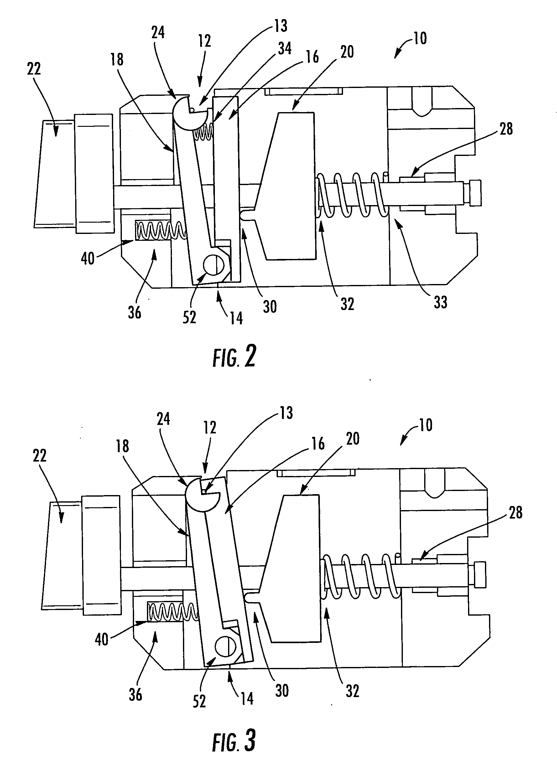
[0020]In various embodiments, the present invention provides an angled optical fiber cleaver that incorporates a novel retention and rotation clamp assembly that successively engages, securely holds, and rotates an optical fiber prior to cleaving, this rotation providing the desired optical fiber endface angle. Advantageously, the novel retention and rotation and clamp assembly of the present invention is actuated via a single linear button press / release, eliminating the cumbersome steps associated with conventional devices and methodologies.

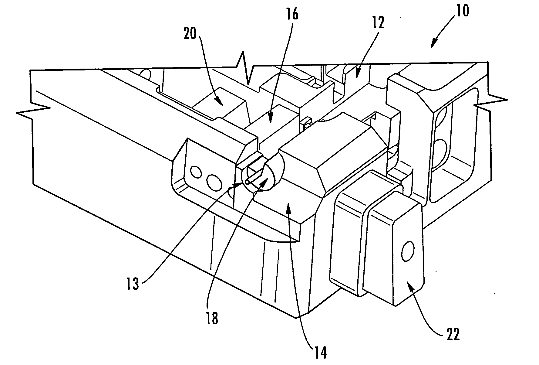
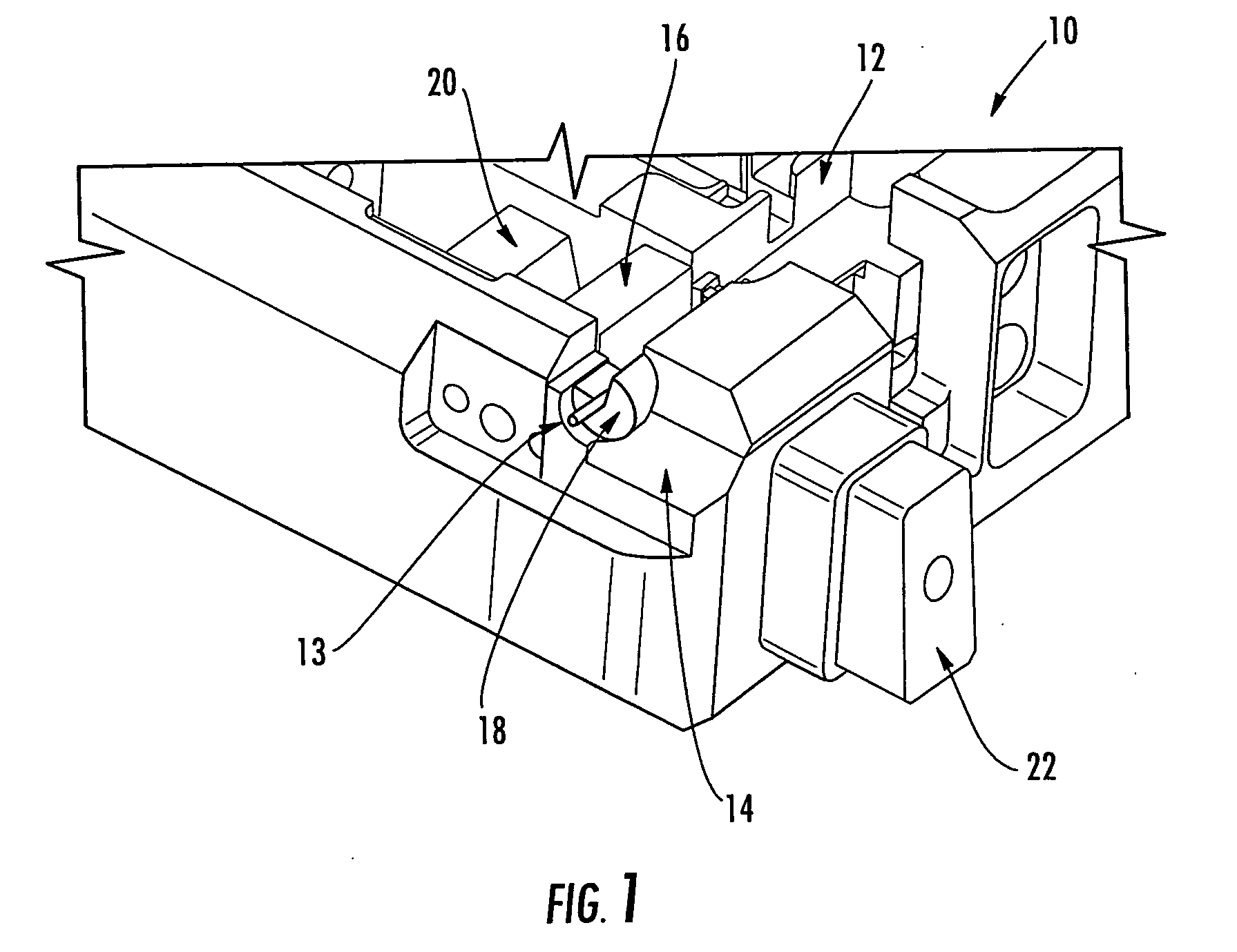
[0021]Referring to FIG. 1, in one embodiment, the angled optical fiber cleaver 10 of the present invention includes a channel 12 configured to receive an optical fiber 13 and a retention and rotation clamp assembly 14 that is disposed partially within the channel 12, the retention and rotation clamp assembly 14 operable for selectively retaining and rotating the optical fiber 13. As is described in greater detail herein below, the retention and ...


PUM


Abstract

The present invention relates generally to an angled optical fiber cleaver that is used to cleave optical fibers prior to mechanical splicing and that provides a desired optical fiber endface angle. More specifically, the present invention relates to an angled optical fiber cleaver that incorporates a novel retention and rotation clamp assembly that successively engages, securely holds, and rotates an optical fiber prior to cleaving, this rotation providing the desired optical fiber endface angle. Advantageously, the novel retention and rotation and clamp assembly of the present invention is actuated via a single linear button press / release, eliminating the cumbersome steps associated with conventional devices and methodologies.

Description

BACKGROUND OF THE INVENTION[0001]1. Field of the Invention[0002]The present invention relates generally to an angled optical fiber cleaver that is used to cleave optical fibers prior to mechanical splicing and that provides a desired optical fiber endface angle. More specifically, the present invention relates to an angled optical fiber cleaver that incorporates a novel retention and rotation clamp assembly that successively engages, securely holds, and rotates an optical fiber prior to cleaving, this rotation providing the desired optical fiber endface angle. Advantageously, the novel retention and rotation and clamp assembly of the present invention is actuated via a single linear button press / release, eliminating the cumbersome steps associated with conventional devices and methodologies.[0003]2. Technical Background of the Invention[0004]Mechanical splice connectors typically require that the spliced optical fibers connected thereby, such as 125 μm optical fibers or the like, ea...

Claims


Application Information

Patent Timeline
Patent Type & Authority Applications(United States)
IPC IPC(8): G02B6/00
CPCG02B6/25
Inventor BRINSON, JONATHAN MICHAELRAKER, JOSHUA DOUGLAS
Owner CORNING OPTICAL COMM LLC
Why Eureka
Try Eureka