
Separable blade for wind turbine

a technology of wind turbines and blades, which is applied in the manufacture of final products, machines/engines, mechanical equipment, etc., can solve the problems of aerodynamic performance and noise increase weight and cost,

Inactive Publication Date: 2008-10-02
HITACHI LTD
View PDF4 Cites 42 Cited by
  • Summary
  • Abstract
  • Description
  • Claims
  • Application Information

AI Technical Summary

Benefits of technology

[0032]In the present invention, a portion of the fastener is exposed at the blade surface as a lightning receptor part, and is connected to a lightning discharge conductive wire in a blade inner portion. The present invention was the result of contemplation on the problems with the prior art described above, and the object thereof is to provide a light and economical separable blade for a wind turbine that is also equipped with a lightning rod function.

Problems solved by technology

In this case, a connecting member is required when the part blades are connected together, which is undesirable not only because of the precision required in the machining thereof, but because of the additional cost and weight.
Connecting in this way forms a large number of protruding parts on the surface of the blade, causing problems in terms of aerodynamic performance and noise.
Additionally, this ties to increased weight and cost, the same as with the technology described in Japanese Unexamined Patent Application Publication 2004-11616.
Additionally, when the connecting members between part blades are secured by a metal frame, as described in Japanese Unexamined Patent Application Publication 2003-214322, this not only leads to increased weight and cost, but also to concerns about problems such as resonant frequencies and abrupt changes in stiffness (concentration of stresses).
Hereupon, blades comprising a non-conductive material such as FRP differ from metallic blades and if struck by lightning, there is danger that the lightning bolt current will not be able to dissipate to ground resulting in damage.
Recently, the increasing sizes of wind turbines which use FRP has resulted in increasing occurrences of damage due to lightning.
Although this metal plate functions as a lightning receptor, there is still the problem of the provision of the metal plate leading to increased cost and weight.

Method used


Image

  • Separable blade for wind turbine
  • Separable blade for wind turbine
  • Separable blade for wind turbine

Examples


Embodiment Construction

[0042]An embodiment of the present invention will be described below in accordance with accompanying drawing. The below is one embodiment of the present invention, and not intended to limit the present invention.

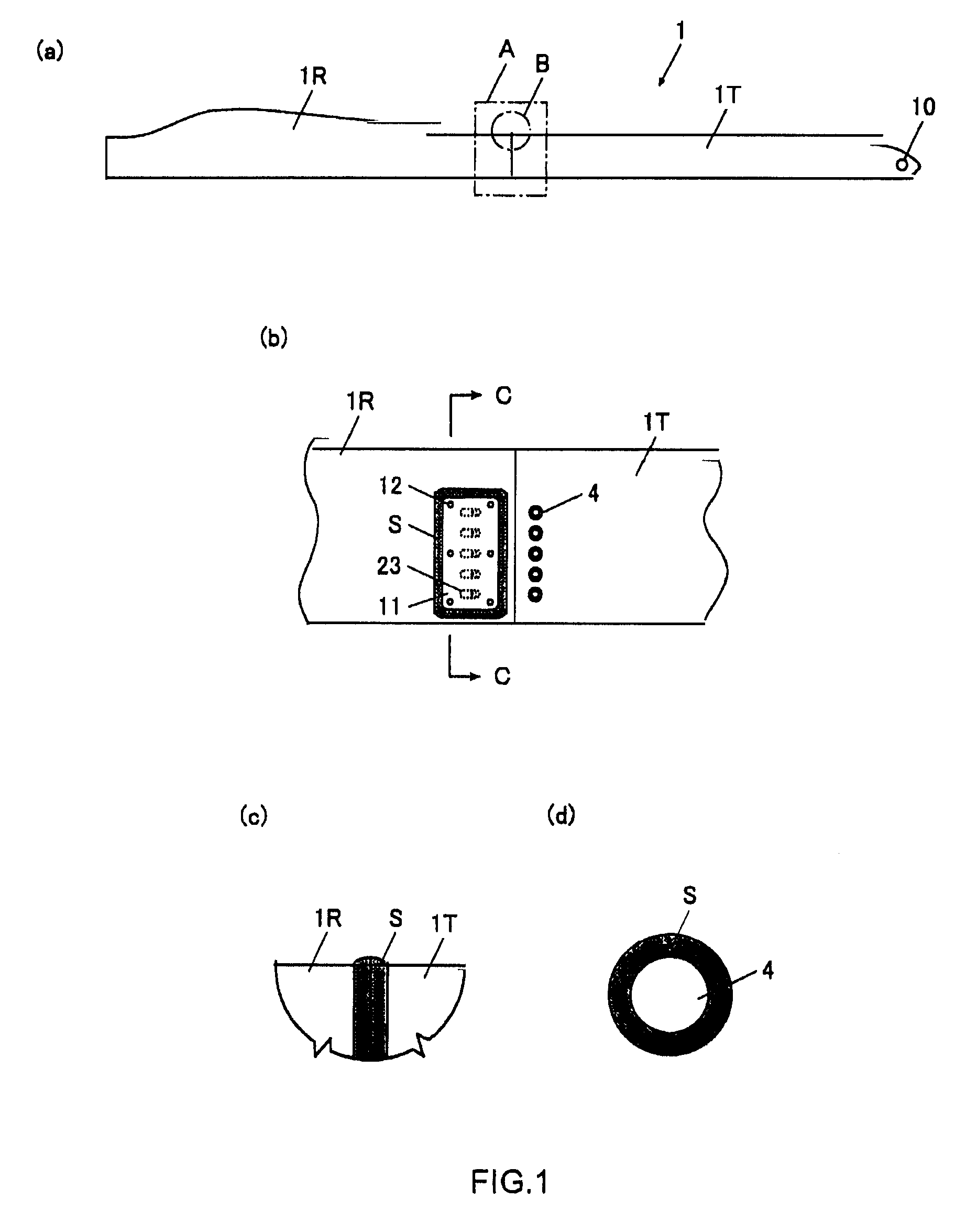
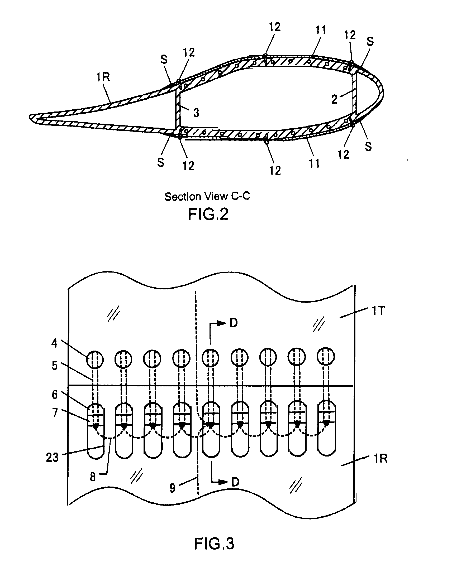
[0043]FIG. 1 (a) is an overall view of a separable blade as set forth in one embodiment of the present invention. FIG. 1 (b) is a detail view of part A; FIG. 1 (c) is a detail view of part B; and FIG. 1 (d) is an expanded view of the exposed surface of the first fastener. FIG. 2 is a cross-sectional diagram along section C-C shown in FIG. 1 (b). FIG. 3 is a plan view schematic diagram of the connector part, and FIG. 4 is a cross-sectional diagram along section D-D.

[0044]As a shown in FIG. 1 and FIG. 2, the separable blade 1 of the present embodiment is structured from a first part blade 1T on the blade tip side, and a second part blade 1R on the blade root side. The part blades 1T and 1R are made from a non-electrically conductive material such as FRP, and, as shown in FIG. ...


PUM


Abstract

To provide a light and economical separable blade for a wind turbine that is also equipped with a lightning rod function. A separable blade for a wind turbine wherein the blade as a whole is assembled by connecting two electrically non-conductive part blades 1T and 1R in the lateral direction, comprising metal fasteners 4, 5, 6, and 7 for fastening together the two adjacent part blades, and lightning discharge conductive wires 8 and 9, provided in an inner blade portion. The fastener 4 is exposed on the blade surface of the part blade 1T, and is connected to the lightning discharge conductive wire 9 through the other fasteners 5, 6, and 7, or a lightning discharge conductive wire 8. The lightning discharge conductive wire 9 extends to the blade root.

Description

CROSS REFERENCE TO RELATED APPLICATIONS[0001]This application claims priority under 35 U.S.C. 119 based upon Japanese Patent Application Serial No. 2007-012504, filed on Jan. 23, 2007. The entire disclosure of the aforesaid application is incorporated herein by reference.FIELD OF THE INVENTION[0002]The present invention relates to the fastening of separable blades for wind turbines, and the lightning protection structures thereof.BACKGROUND OF THE INVENTION[0003]It is well known that so-called horizontal axis wind turbines are widely used in wind power generation systems. An ordinary horizontal axis wind turbine is comprised by a rotor whereon at least two or more blades are radially attached from a hub, a nacelle that is connected to the hub and axially supports this rotor through a main shaft that is extended in an approximate horizontal direction, and a tower that is installed in an approximate vertical direction and supports the nacelle in a yaw rotatable state.[0004]Recently pr...

Claims


Application Information

Patent Timeline
IPC IPC(8): F01D5/14
CPCF03D1/0675F03D11/00F03D11/0033F05B2230/50F05B2240/30F05B2240/302F05B2260/301Y02E10/721Y02E10/722F03D80/00F03D80/30Y02E10/72Y02P70/50
Inventor KITA, MASAKAZUKOMINATO, YUKI
Owner HITACHI LTD
Learn More