Heart imaging with adaptive inversion time

a heart and inversion time technology, applied in the field of heart imaging with adaptive inversion time, can solve the problem that it is not possible to fill the entire raw data space, and achieve the effect of improving the contrast of inversion-prepared imaging methods and a longer time period

Inactive Publication Date: 2008-10-02
SIEMENS HEALTHCARE GMBH
View PDF12 Cites 36 Cited by
  • Summary
  • Abstract
  • Description
  • Claims
  • Application Information

AI Technical Summary

Benefits of technology

[0005]An object of the present invention is to improve the contrast in inversion-prepared imaging methods

Problems solved by technology

In this short time it is normally not po

Method used


Image

  • Heart imaging with adaptive inversion time
  • Heart imaging with adaptive inversion time
  • Heart imaging with adaptive inversion time

Examples


Embodiment Construction

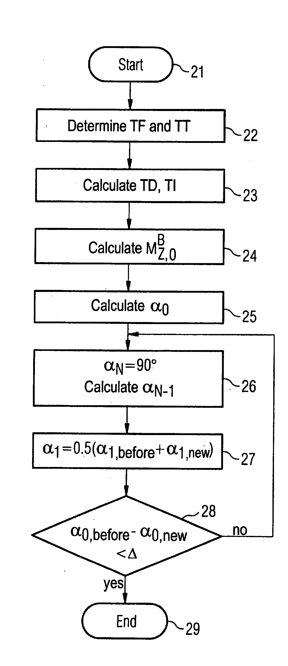
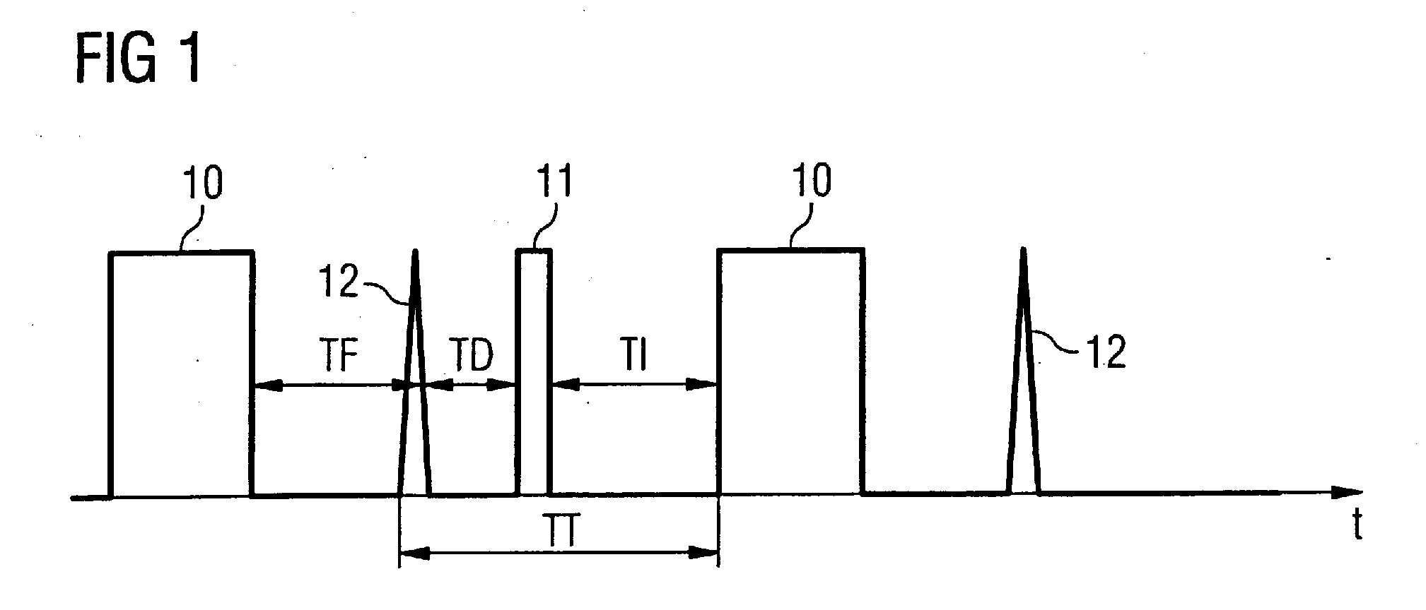
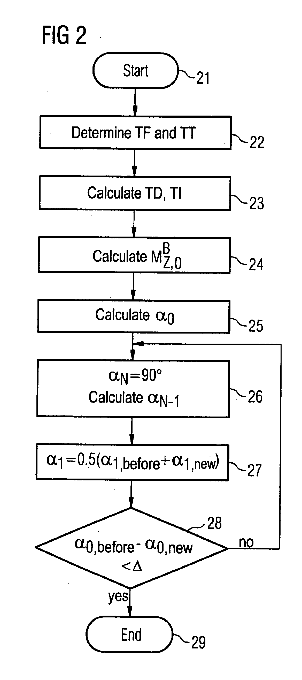
[0014]A sequence diagram is schematically shown in FIG. 1. The acquisition of the MR signals ensues during the blocks 10. In one exemplary embodiment of the invention the imaging sequence is a spoiled gradient echo sequence with an inversion pulse that is schematically represented with reference character 11. The imaging sequence is a segmented imaging sequence, such that only N RF pulses with the flip angle α are respectively radiated during the blocks 10. As described in detail further below, the flip angles α are not constant, rather they become larger within a block 10. Furthermore, the R-spike 12 of the EKG signal is shown in FIG. 1. This R-spike serves as a trigger for the selection of the point in time for switching of the inversion pulse and the RF excitation pulses. The time spans shown in FIG. 1 are defined as follows. The time span TF is the fill time after the signal readout until the next R-spike. The time span TD runs from the R-spike until the switching of the RF inve...


PUM


Abstract

In a method for acquisition of magnetic resonance images of the heart, MR signals of the heart are acquired using an imaging sequence, wherein the magnetization is inverted by an RF inversion pulse before the acquisition of the MR signals; and of the heart activity is detected, and the point in time of the switching of the RF inversion pulse dependent on the detected heart activity.

Description

BACKGROUND OF THE INVENTION[0001]1. Field of the Invention[0002]The present invention concerns a method for acquisition of magnetic resonance images of the heart. The invention is in particular suited for use in imaging methods in which contrast agent is injected into the body in order to be able to intensify the contrast in the image of the heart.[0003]2. Description of the Prior Art[0004]Usually, in contrast agent-intensified heart imaging, an RF inversion pulse is emitted before the imaging in order to invert the magnetization by 180 degrees from the equilibrium state (steady state). Since the contrast agent in the blood significantly shortens the T1 relaxation time, an intensified contrast can be achieved between the blood in the heart and the myocardium. In known imaging methods of the heart, most imaging parameters are unalterable, once. Changes of the heart rate or the relaxation times of the tissue of interest have previously not been taken into account during the execution ...

Claims


Application Information

Patent Timeline
IPC IPC(8): A61B5/055A61B5/352
CPCA61B5/055A61B5/7285G01R33/5601G01R33/5602A61B5/0456G01R33/5635G01R33/56509G01R33/5673G01R33/5607A61B5/352
Inventor WARMUTH, CARSTEN
Owner SIEMENS HEALTHCARE GMBH
Why Eureka
Try Eureka