Electrostatically driven image probe

a technology of image probe and drive motor, which is applied in the direction of sound producing devices, sensors, catheters, etc., can solve the problems of electrostatic discharge, difficult engineering challenges in the cavity of the body, forward looking imaging devices for viewing small (1-20 mm) lumens,

Inactive Publication Date: 2008-10-02
UNIV HEALTH NETWORK
View PDF14 Cites 34 Cited by
  • Summary
  • Abstract
  • Description
  • Claims
  • Application Information

AI Technical Summary

Benefits of technology

[0015]c) an elongate electrode located in the elongate hollow catheter sheath having an elongate uninsulated electrode section located in said front distal section, the elongate electrode being connected to a high voltage power supply, wherein in operation when a high voltage is applied to the elongate electrode the cantilever is electrically attracted to the elongate uninsulated electrode section and undergoes deflection towards the elongate uninsulated electrode section and upon contacting the elongate uninsulated electrode section the portion of the metal enveloped imaging conduit in the distal front section acquires an electrical charge from the elongate uninsulated electrode section thereby causing the metal enveloped imaging conduit in the distal front section to be repelled therefrom thereby causing the imaging means to scan the field of view.

Problems solved by technology

Forward looking imaging devices for viewing small (1-20 mm) lumens, orifices, and cavities of the body remain a difficult engineering challenge.
This direct connection to ground of the cantilever is problematic resulting in significant electrostatic discharge given the high voltage necessary to oscillate a rigid fiber.

Method used


Image

  • Electrostatically driven image probe
  • Electrostatically driven image probe
  • Electrostatically driven image probe

Examples


Embodiment Construction

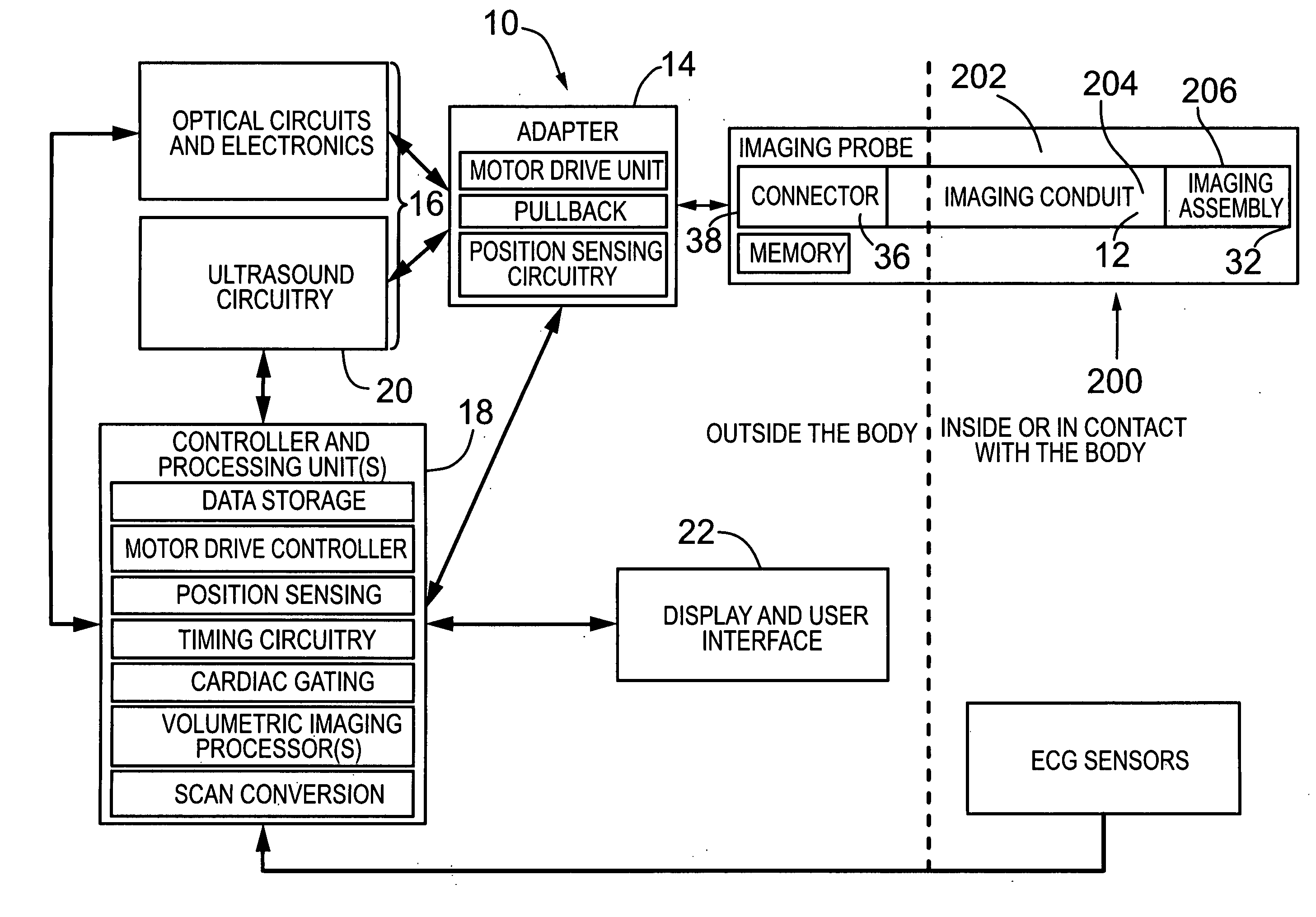
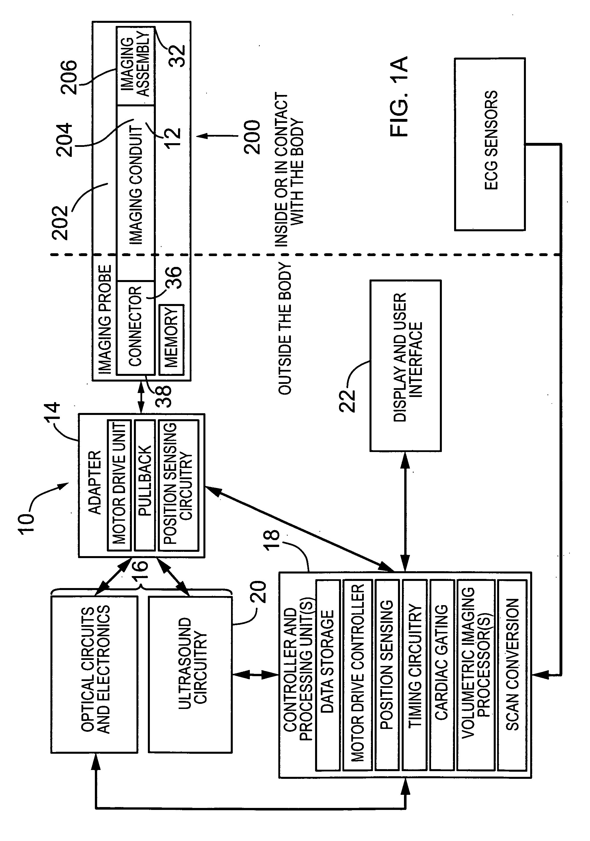
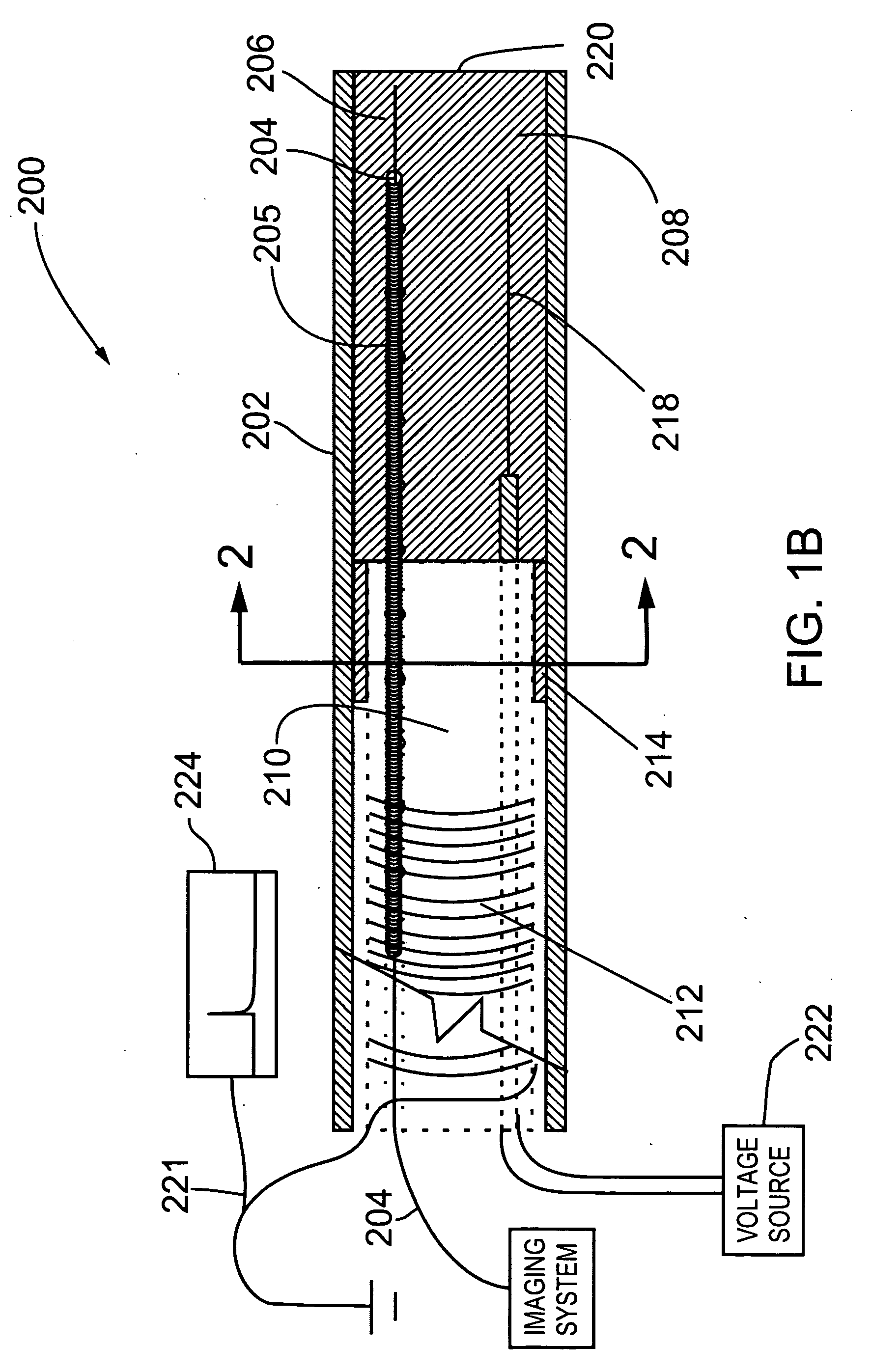
[0062]Generally speaking, the systems described herein are directed to an imaging probe using either optical or ultrasonic (or both) imaging. As required, embodiments of the present invention are disclosed herein. However, the disclosed embodiments are merely exemplary, and it should be understood that the invention may be embodied in many various and alternative forms. The Figures are not to scale and some features may be exaggerated or minimized to show details of particular elements while related elements may have been eliminated to prevent obscuring novel aspects. Therefore, specific structural and functional details disclosed herein are not to be interpreted as limiting but merely as a basis for the claims and as a representative basis for teaching one skilled in the art to variously employ the present invention. For purposes of teaching and not limitation, the illustrated embodiments are directed to an imaging probe.

[0063]As used herein, the terms “about”, and “approximately” ...


PUM


Abstract

The present invention provides an imaging probe for imaging mammalian tissues and structures using high resolution imaging, including ultrasound and optical coherence tomography. The imaging probe uses electrostatic discharge for actuating a metalized cantilever which holds the end portion of imaging assembly which emits energy in the imaging probe device by holding the cantilever at a potential such that it is neither grounded or charged such that the only electrical path to ground is through a dissipative polymer forming part of the device which is enveloped by a wire or coil held at ground potential. A high voltage electrode attracts the metalized cantilever and the dissipative polymer is used to connect to the cantilever to ground causing the cantilever to move about thereby scanning the region in front of the probe.

Description

CROSS REFERENCE TO RELATED U.S. APPLICATION[0001]This patent application relates to, and claims the priority benefit from, U.S. Provisional Patent Application Ser. No. 60 / 881,169 filed on Jan. 19, 2007, in English, entitled IMAGING PROBE, which is incorporated herein by reference in its entirety.FIELD OF THE INVENTION[0002]The present invention relates generally to the field of imaging mammalian tissues and structures using high resolution imaging, including high frequency ultrasound and optical coherence tomography using electrostatic forces to generate motion of a scanning mechanism which is coupled to ground through a dissipative polymer to thereby scan regions of interest.BACKGROUND OF THE INVENTION[0003]Forward looking imaging devices for viewing small (1-20 mm) lumens, orifices, and cavities of the body remain a difficult engineering challenge. In many instances, the forward looking imaging geometry is, however, more amenable to providing interventional guidance than conventio...

Claims


Application Information

Patent Timeline
Patent Type & Authority Applications(United States)
IPC IPC(8): A61B8/00A61B5/00
CPCA61B5/0062A61B5/742A61B5/0095A61B5/6852A61B8/12A61B8/4281A61B8/4461A61B8/5238A61B8/543A61B1/00172A61B1/00183A61B8/483A61B8/445A61B5/0035A61B8/5292A61B5/0084A61B5/7207A61B5/0066G10K11/002A61B2562/0233A61B1/00112G02B6/3604G02B23/2423A61B1/05A61B1/04
Inventor MUNCE, NIGEL ROBERTYANG, VICTOR XIAO DONGCOURTNEY, BRIANTHIND, AMANDEEP SINGH
Owner UNIV HEALTH NETWORK
Why Eureka
Try Eureka