Ultrasound probe with progressive element sizing

a technology of element sizing and ultrasonic probe, which is applied in the direction of mechanical vibration separation, instruments, catheters, etc., can solve the problems of increasing sensor cost with the number of elements in the array and the number of processing channels, and not being practicable for blood velocity monitoring in the intensive care unit (icu) of surgical applications

Inactive Publication Date: 2002-10-17
PHYSIOSONICS
View PDF0 Cites 49 Cited by
  • Summary
  • Abstract
  • Description
  • Claims
  • Application Information

AI Technical Summary

Problems solved by technology

However, blood velocity monitoring is not currently practical for intensive care unit (ICU) of surgical applications.
Slight movements cause the probe to lose the blood velocity signal.
However, in order for a two dimensional (2-D) device to provide such imaging normally requires thousands of elements, and must form many thousands of pencil beams every {fraction (1/30)} second.
Sensor cost grows with the number of elements

Method used


Image

  • Ultrasound probe with progressive element sizing
  • Ultrasound probe with progressive element sizing
  • Ultrasound probe with progressive element sizing

Examples


Embodiment Construction

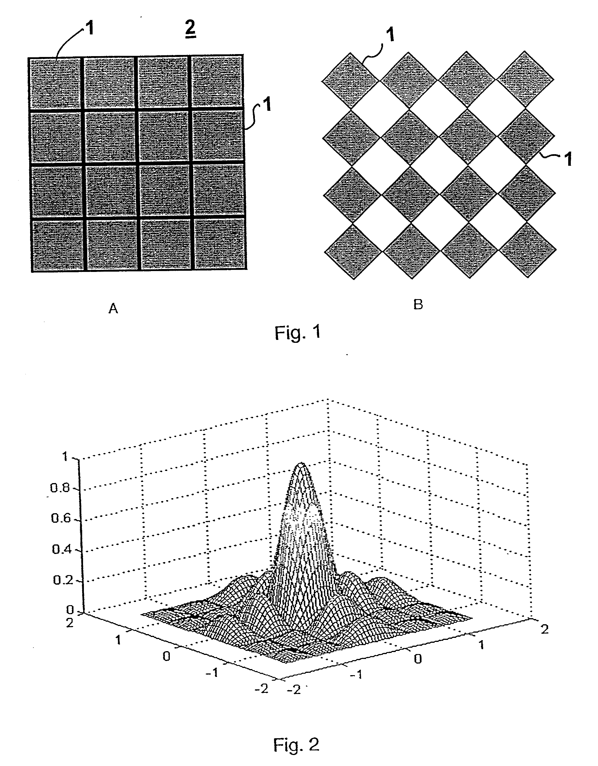
[0053] For simplicity, assume an example of a square array of uniformly spaced transmitters and receivers 1, where the receivers lie on a N by N grid 2, at a spacing of d for both the horizontal and vertical directions. In this case, the transmitters illustrated in FIG. 1 would each be 2d wide and 2d high. High-resolution dynamic volumetric imaging, could, for example, require a 16 by 16 receiver array and hence an 8 by 8 array of 64 transmitters (N=16). The two-dimensional amplitude pattern of a 2d by 2d square transmitter aperture is plotted as a function of x=(d / .lambda.) sin .o slashed. in FIG. 2.

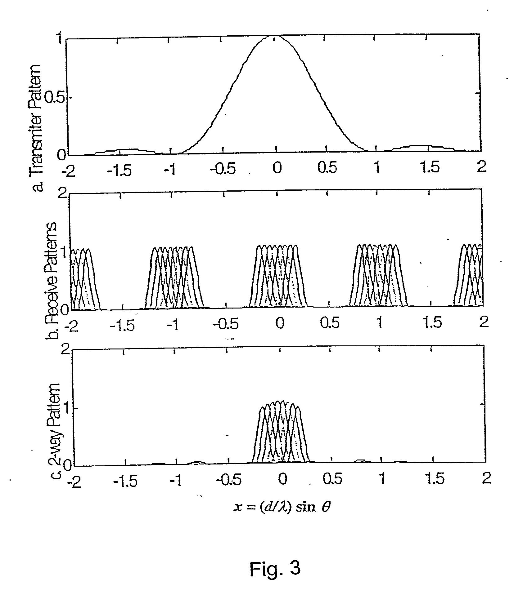
[0054] Since the receivers are not directive by themselves, suppression of grating lobes must be accomplished entirely by the transmitter pattern. Hence triangular shading can be used to produce a low-side lobe (sin .pi.x / .pi.x) .sup.2 pattern in both x and y (corresponding to azimuth and elevation) This is illustrated in FIG. 3, (showing azimuth only) for the case of N=16 .

[0055] For e...


PUM


Abstract

A prior application discloses a novel probe geometry that offers a wide field of view in an ultrasonic imaging device. That geometry is referred to as a "thinned array" of transducer elements. The application discloses an improved probe geometry permitting high-resolution imaging of a large volume of the subject's body. In this improved geometry, the array elements are non-uniform in size and spacing. The probe is intended for use, for example, in a method of determining parameters of blood flow, such as vector velocity, blood flow volume, and Doppler spectral distribution, using sonic energy (ultrasound) and a novel thinned array. Also in a method of tracking blood flow and generating a three dimensional image of blood vessel of interest that has much greater resolution than images produced using heretofore known ultrasound devices and methods.

Description

[0001] 1. Field of the Invention[0002] The present invention involves an ultrasound Doppler method that permits non-invasive diagnosis and non-invasive unattended, continuous monitoring of vascular blood flow for medical applications.[0003] 2. Brief Description of the Background Art[0004] Acoustic Doppler blood velocity measurement is a known medical diagnostic tool. The phased array steering of the acoustic beam and the phased array listening for the Doppler frequency-shifted echo are techniques that derive from a large body of work in the field of phased-array radar systems. The Doppler frequency shifts result from reflection of the transmitted acoustic beam from the moving blood constituents and are related in a known way to the velocity of blood flows. However, blood velocity monitoring is not currently practical for intensive care unit (ICU) of surgical applications. For non-invasive brain blood velocity monitoring, for example, a transcranial Doppler (TCD) probe must be mounte...

Claims


Application Information

Patent Timeline
IPC IPC(8): A61B8/06B06B1/06G01S15/89
CPCA61B8/06A61B8/4483G01S15/8925B06B1/0622A61B8/483
Inventor ABEND, KENNETH
Owner PHYSIOSONICS
Why Eureka
Try Eureka