Spectroscopic pupil laser confocal Raman spectrum testing method and device

A technology of spectrum testing and Raman spectroscopy, which is applied in the field of microspectral imaging, can solve problems such as reduced focus accuracy, single mode, and instrument system drift, and achieve the effect of suppressing errors and improving measurement accuracy

Active Publication Date: 2013-12-11
BEIJING INSTITUTE OF TECHNOLOGYGY
View PDF7 Cites 50 Cited by
  • Summary
  • Abstract
  • Description
  • Claims
  • Application Information

AI Technical Summary

Problems solved by technology

[0004] Because the excited Raman scattered light is very weak, in order to reduce the energy loss of Raman scattered light in the existing laser confocal Raman spectrometer, a larger pinhole is selected in the system, usually between φ150μm and φ200μm. The system uses the confocal method for focus positioning. The size of the pinhole directly affects the half-height width of the confocal axial positioning curve. The larger the size of the pinhole, the lower the accuracy of the system's focus, which reduces the spatial resolution.
And the system can only perform spectral detection, and the mode is single, which limits its application field
[0005] At the same time, the Raman scattered light scattered by the sample is only 10 times the intensity of the reflected Rayleigh beam. -3 ~10 -6 times, while the existing confocal Raman spectroscopic detection instruments only use weak Raman scattered light for spectral detection and discard stronger than Raman scattered light10 3 ~10 6 times the Rayleigh beam, using Raman scattered light for direct imaging, there is a disadvantage of low system sensitivity
[0006] In addition, in order to obtain accurate and rich measurement information, Raman spectral imaging requires both single-point Raman spectral detection and multi-point Raman spectral detection for a long time, so Raman spectral imaging requires a long time
However, during the long-term imaging process of the instrument, it is greatly affected by ambient temperature, vibration, air jitter, etc., which may easily cause the instrument system to drift, which will cause the sample to be detected out of focus; because the existing confocal Raman spectroscopy detection technology does not have Real-time focus tracking and position correction capabilities, so during the entire imaging process, the position of the excitation spot cannot be guaranteed to be at the focal point of the objective lens. The actual excitation spot is much larger than the focus spot of the objective lens, which restricts the miniaturization of the detectable area. Limiting the Micro-region Spectral Detection Capabilities of Confocal Raman Spectroscopy Instruments

Method used


Image

  • Spectroscopic pupil laser confocal Raman spectrum testing method and device
  • Spectroscopic pupil laser confocal Raman spectrum testing method and device
  • Spectroscopic pupil laser confocal Raman spectrum testing method and device

Examples


Embodiment

[0062] In this embodiment, the dichroic spectroscopic system 6 is a Notch filter, the spectrum detector 9 is a Raman spectrum detector, the image acquisition system 13 is a CCD, and the image magnification system 27 is a magnifying objective lens.

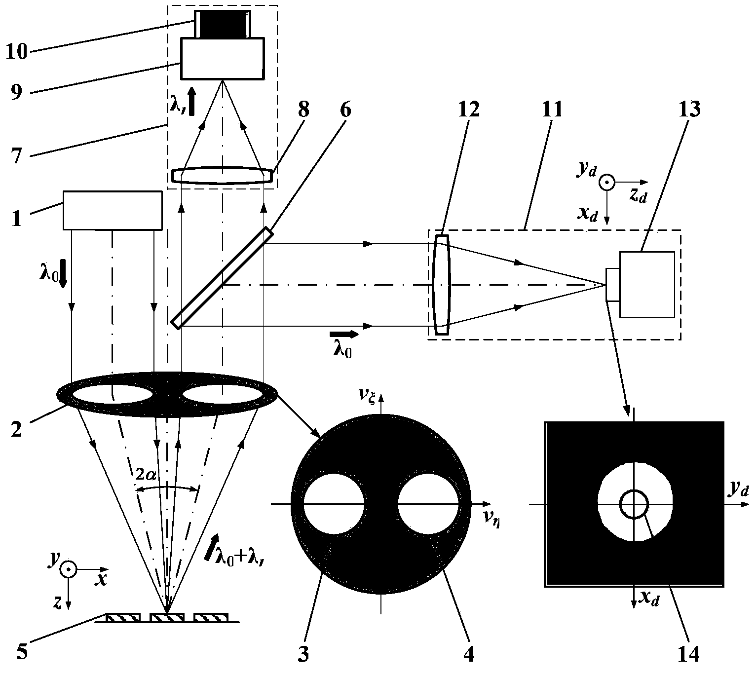
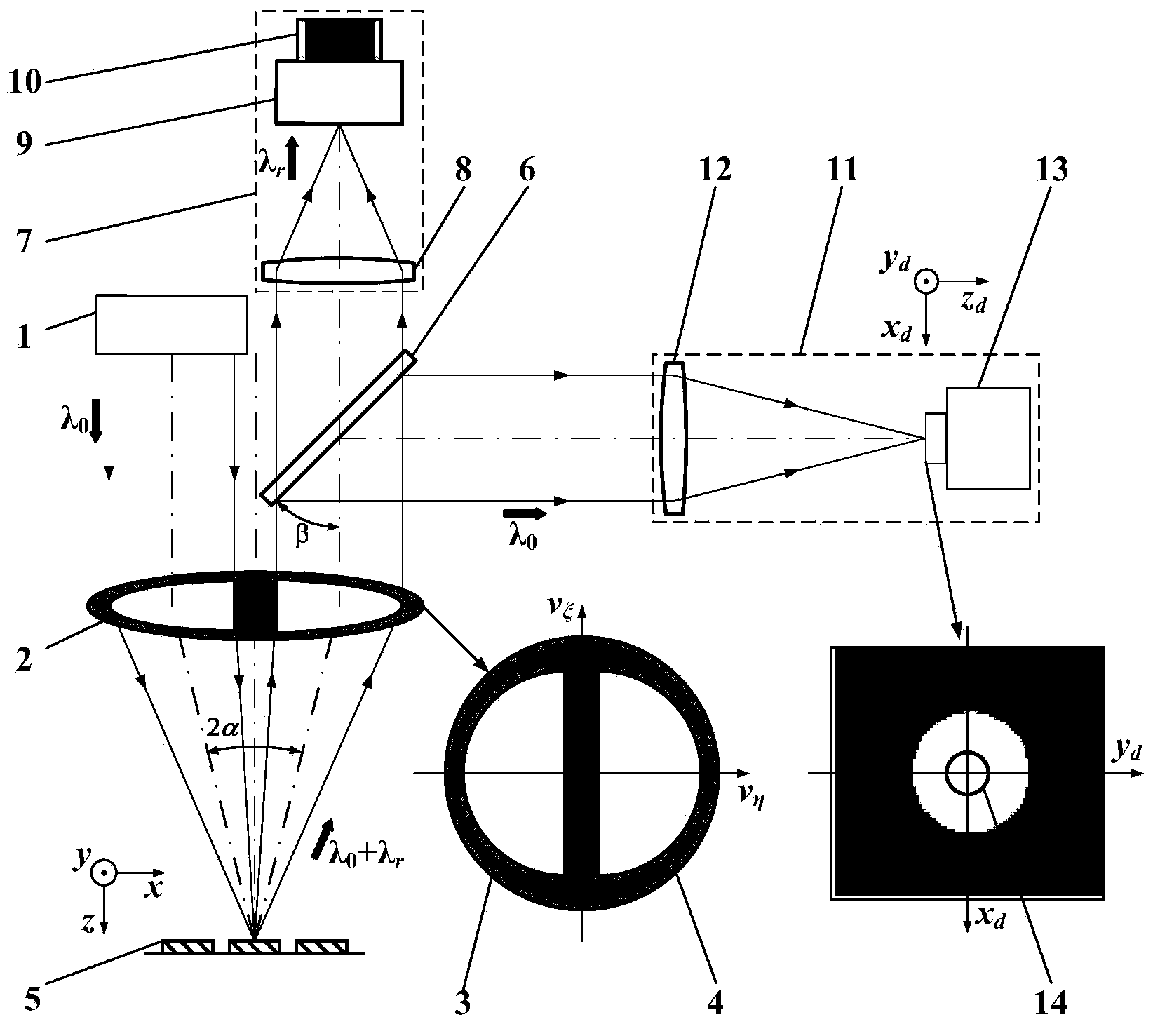
[0063] Such as Figure 8 As shown, the detection process of the split pupil laser confocal Raman spectrum is as follows:

[0064] First, the light source system 1 composed of lasers emits excitation light that can excite the Raman spectrum of the sample under test. The excitation light is condensed by the third condenser lens 24 and then enters the second pinhole 25 to become a point light source, which is collimated and expanded by the fourth condenser lens 26. After the beam, a parallel excitation beam is formed. After the excitation light beam passes through the illumination pupil 3 and the measuring objective lens 2, it is focused on the sample 5 to be tested, and the Raman scattered light carrying the spectral characteristics of th...


PUM


Abstract

The invention belongs to the technical field of microscopic spectrum imaging, and relates to a spectroscopic pupil laser confocal Raman spectrum testing method and device, wherein a confocal microscopic technology and a Raman spectrum detecting technology are combined. A spectroscopic pupil confocal microscopic imaging system is constructed by using rayleigh scattering light discarded in confocal Raman spectrum detection, high-resolution imaging and detection of a three-dimensional geometric position of a sample are realized; and a spectrum detection system is controlled by using an extreme point of the spectroscopic pupil confocal microscopic imaging system to be capable of accurately capturing Raman spectrum information excited by a focusing point of an objective lens, and further spectroscopic pupil confocal Raman spectrum high-space-resolution imaging and detection of image and spectrum integration are realized. The spectroscopic pupil laser confocal Raman spectrum testing method and device provide a new technical approach for high-space-resolution detection of the three-dimensional geometrical position and spectrum in a microcell, can be widely applied to the fields such as physics, chemistry, biomedicine, material science, environmental sciences, petrochemical engineering, geology, medicines, foods, criminal investigation and jewelry verification, and are capable of carrying out nondestructive identification and deep spectrum analysis of a sample.

Description

Technical field [0001] The invention belongs to the field of microscopic spectral imaging technology, combines confocal microscopy technology with Raman spectroscopy detection technology, and relates to a "pattern-in-one" high-spatial-resolution spectral test imaging method and device, which are used to measure the micro-zone spectrum of a sample Perform high-resolution testing, etc. Background technique [0002] Laser confocal Raman spectroscopy technology uses incident laser to cause molecules (or lattices) to vibrate and lose (or gain) part of the energy, which changes the frequency of scattered light. By analyzing the scattered light, the composition and structure of molecules can be detected. And relative content, laser confocal Raman spectroscopy technology is also called molecular probe technology. This technology not only inherits the high-resolution tomography characteristics of confocal microscopy, but also can perform spectral analysis on samples. It can not only obse...

Claims


Application Information

Patent Timeline
Patent Type & Authority Applications(China)
IPC IPC(8): G01N21/00G01N21/65
Inventor 赵维谦王允刘大礼盛忠
Owner BEIJING INSTITUTE OF TECHNOLOGYGY
Why Eureka
Try Eureka