Thermal sensation determining apparatus and method, and air-conditioning control apparatus using thermal sensation determination result

Inactive Publication Date: 2008-10-02
TOSHIBA LIFESTYLE PROD & SERVICES CORP
View PDF1 Cites 18 Cited by
  • Summary
  • Abstract
  • Description
  • Claims
  • Application Information

AI Technical Summary

Benefits of technology

[0011]The present invention provides a thermal sensation determining apparatus and method easily providing a detailed thermal sens

Problems solved by technology

Therefore, these techniques cannot easily determine the thermal sensation or provide detailed determination res

Method used


Image

  • Thermal sensation determining apparatus and method, and air-conditioning control apparatus using thermal sensation determination result
  • Thermal sensation determining apparatus and method, and air-conditioning control apparatus using thermal sensation determination result
  • Thermal sensation determining apparatus and method, and air-conditioning control apparatus using thermal sensation determination result

Examples


first embodiment

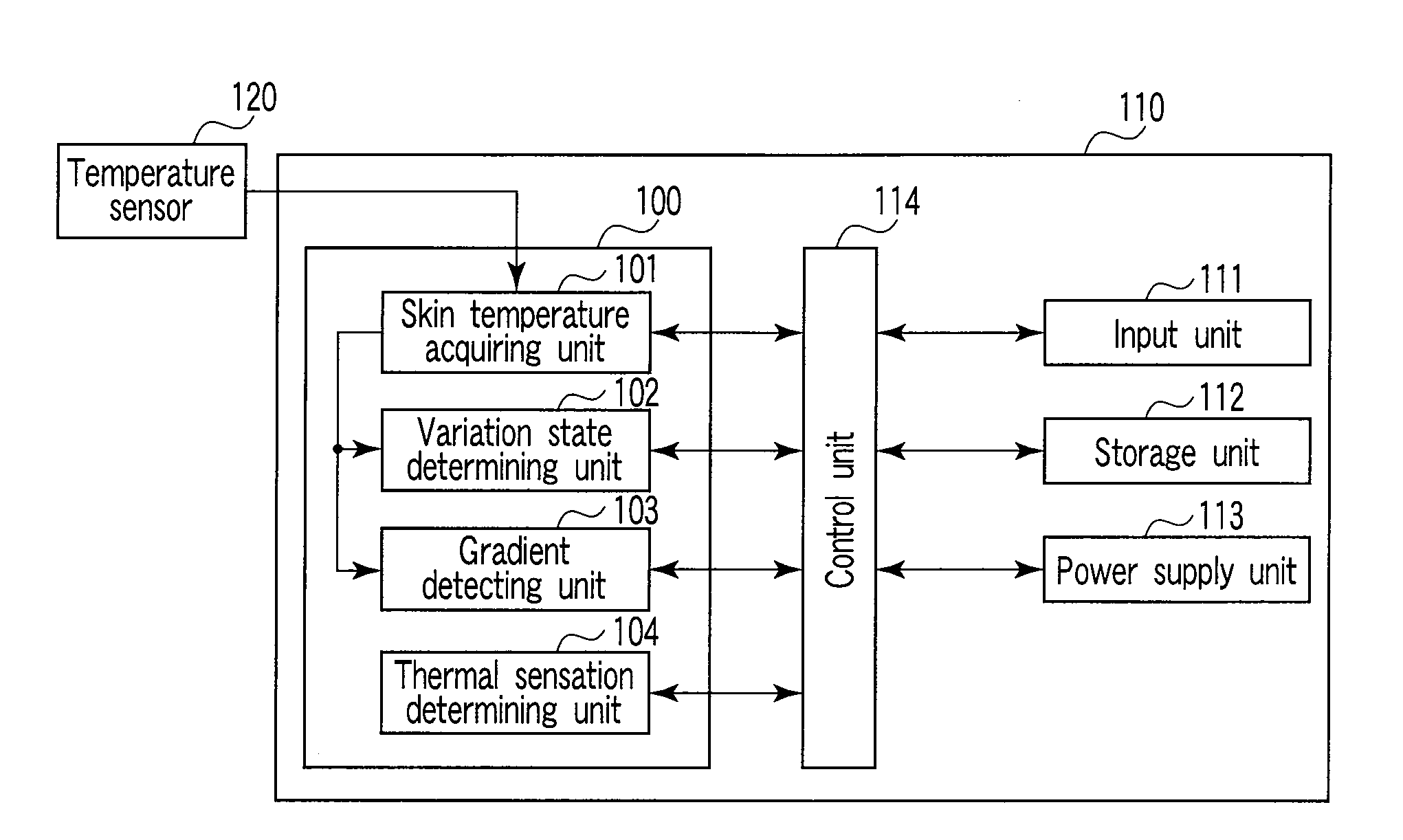
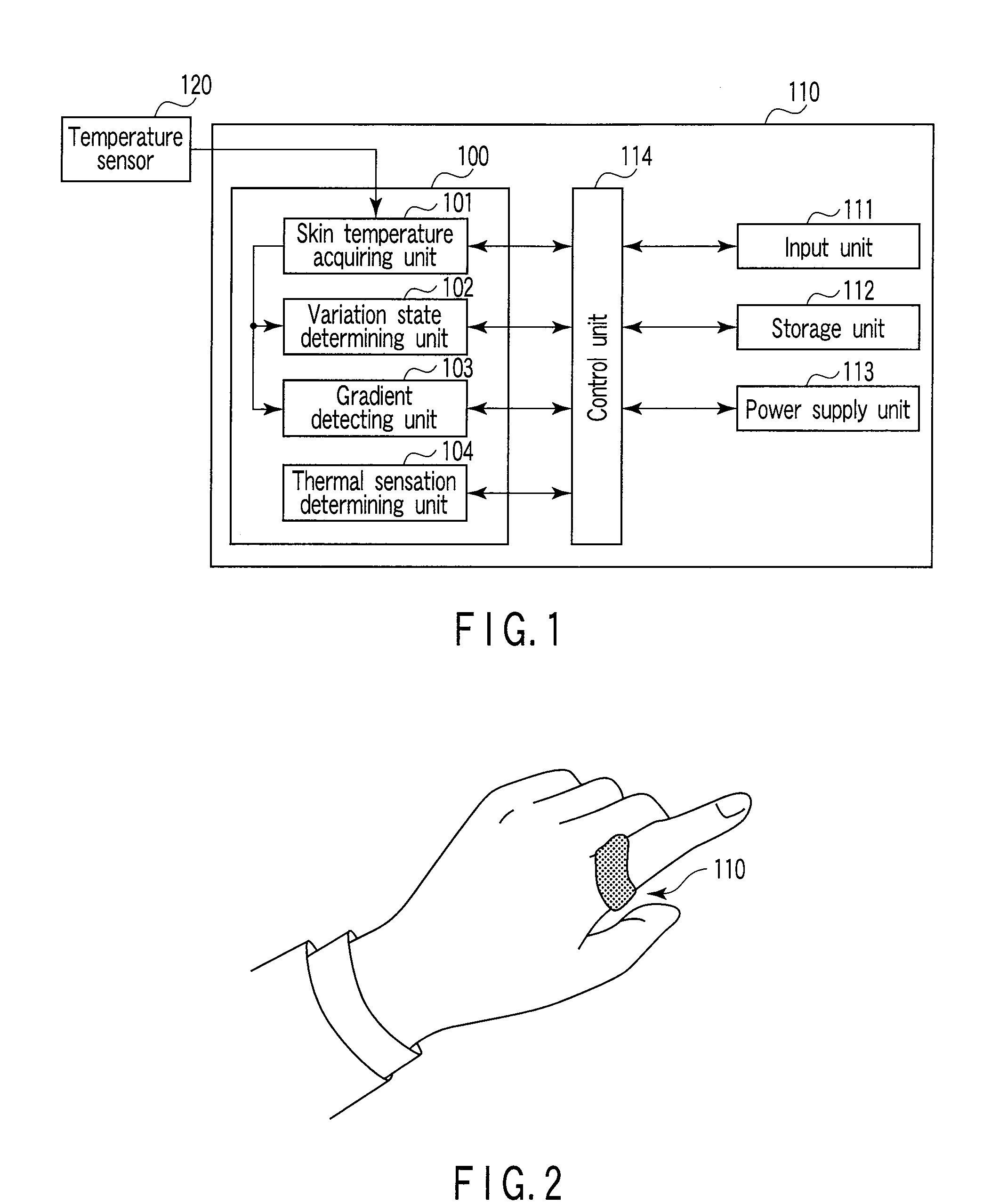
[0038]As shown in FIG. 1, a thermal sensation determining apparatus 100 according to a first embodiment of the present invention has a skin temperature acquiring unit 101, a variation state determining unit 102, a gradient detecting unit 103, and a thermal sensation determining unit 104. The thermal sensation determining apparatus 100 is incorporated in a thermal sensation determining system 110. The thermal sensation determining system 110 has an input unit 111, a storage unit 112, a power supply unit 113, and a control unit 114. A temperature sensor 120 is connected to the thermal sensation determining system 110 to measure the skin temperature of a peripheral part of a subject's body.

[0039]The thermal sensation determining system 110 is formed, for example, like a ring as shown in FIG. 2 and is installed at the base of the subject's finger. The temperature sensor 120 is provided on a surface of the system which is in close contact with the subject's skin. The skin temperature acq...

second embodiment

[0068]As shown in FIG. 13, a thermal sensation determining apparatus 300 according to a second embodiment of the thermal sensation determining apparatus 100 shown in FIG. 1 and further having an environmental temperature acquiring unit 305 and a determination value correcting unit 306. The thermal sensation determining apparatus 300 is incorporated in a thermal sensation determining system 310. A temperature sensor 321 measuring the environmental temperature is connected to the thermal sensation determining system 310. In FIG. 13, the same components as those shown in FIG. 1 are denoted by the same reference numerals and will not be described in detail, and only the differences will be mainly described.

[0069]The environmental temperature acquiring unit 305 continuously acquires the environmental temperature around the subject from the temperature sensor 321. Now, the relationship between the environmental temperature and the thermal sensation will be described. In certain experiment...

third embodiment

[0074]As shown in FIG. 16, a thermal sensation determining apparatus 500 according to a third embodiment of the thermal sensation determining apparatus 100 shown in FIG. 1 and further having a determination value correcting unit 506 and a perspiration detecting unit 507. The thermal sensation determining apparatus 500 is incorporated into a thermal sensation determining system 510. In FIG. 16, the same components as those shown in FIG. 1 are denoted by the same reference numerals and will not be described in detail. Differences from FIG. 1 will be mainly described.

[0075]First, the relationship between perspiration and the thermal sensation will be described. In certain experiments, when the subject's peripheral skin temperature varied as shown in FIG. 17A, the subject felt such thermal sensation as shown in FIG. 17B. The waveform in an interval (the interval during which the subject's thermal sensation is “1” to “2”, that is, “warm” to “a little hot”), specified by an arrow in FIG. ...


PUM


Abstract

A thermal sensation determining apparatus includes a skin temperature detecting unit configured to detect a skin temperature of a peripheral site of a subject's body, a variation state determining unit configured to determine a variation state of the skin temperature during a first interval to obtain a variation state determination result, a gradient detecting unit configured to detect a gradient of the skin temperature during a second interval to determine the gradient to obtain a gradient detection result, and a thermal sensation determining unit configured to determine the subject's thermal sensation using the variation state determination result and the gradient detection result to obtain a thermal sensation determination result classified into levels ranging from “hot” to “cold” based on a “moderate” temperature.

Description

CROSS-REFERENCE TO RELATED APPLICATIONS[0001]This application is based upon and claims the benefit of priority from prior Japanese Patent Application No. 2007-082701, filed Mar. 27, 2007, the entire contents of which are incorporated herein by reference.BACKGROUND OF THE INVENTION[0002]1. Field of the Invention[0003]The present invention relates to a thermal sensation determining apparatus and method utilizing a biological index obtained from a subject, and an air-conditioning control apparatus and method using the thermal sensation determination result.[0004]2. Description of the Related Art[0005]An apparatus that determines a subject's thermal sensation using thermal indices such as SET* (Standard Effective Temperature) and PMV (Predicted Mean Vote) have hitherto been known. However, the use of SET* and PMV requires measuring instruments for measuring environmental indices such as a temperature, air current, radiant heat, the amount of clothing, and the quantity of work. On the ot...

Claims


Application Information

Patent Timeline
IPC IPC(8): A61B5/01
CPCA61B5/01A61B5/7264
Inventor NAKAYAMA, KANAKOSUZUKI, TAKUJIOUCHI, KAZUSHIGEKAMEYAMA, KENICHI
Owner TOSHIBA LIFESTYLE PROD & SERVICES CORP
Why Eureka
Try Eureka