Cardiac stimulation apparatus

a technology of stimulation apparatus and heart wall, which is applied in the field of cardiac stimulation apparatus, can solve problems such as damage to the heart wall

Inactive Publication Date: 2008-10-02
WILDON MICHAEL PETER
View PDF14 Cites 103 Cited by
  • Summary
  • Abstract
  • Description
  • Claims
  • Application Information

AI Technical Summary

Benefits of technology

[0007]In this way there is no trauma to the heart or other tissue caused by the attachment process.
[0012]In another arrangement, electrical stimulation may be delivered to the electrode without the need for a lead to extend through the body of a patient undergoing cardiac stimulation to a source of electrical stimulation external to the body of the patient.
[0021]On the other hand, the lead or at least part thereof may be constructed of biocompatible bio absorbable material, thereby eliminating the need to remove the lead from the body of the patient.
[0037]With this arrangement, it is not necessary for the substrate to be removed from the patient at the time of removal of the electrode and any lead attached thereto.

Problems solved by technology

Such techniques for retaining the electrode or electrode assembly in electrical contact with the heart wall can cause damage to the heart wall, not only during the attachment phase but possibly also during the subsequent detachment phase as the lead is withdrawn from the body of the patient by a pulling process.

Method used


Image

  • Cardiac stimulation apparatus
  • Cardiac stimulation apparatus
  • Cardiac stimulation apparatus

Examples


first embodiment

[0079]As there is only one electrode sufficiently large enough for use in defibrillation procedures, the epicardial stimulating lead can only be employed for monopolar defibrillation.

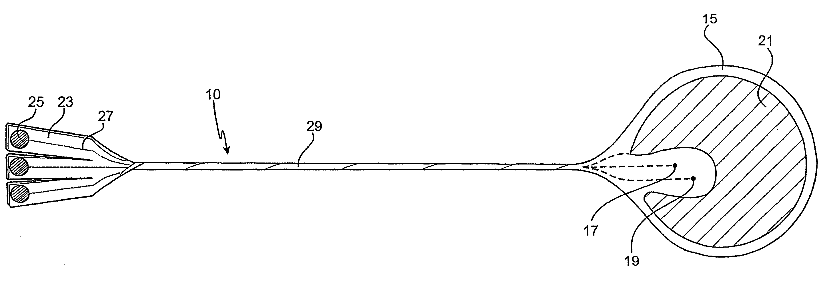
[0080]The epicardial stimulation lead according to the second embodiment, which is shown in FIGS. 5, 6 and 7 is similar to the first embodiment with the exception that there are four electrodes, being a pair of small electrodes 17 and 19 for use in cardiac pacing and a pair of large electrodes 21 for use in bipolar defibrillation.

second embodiment

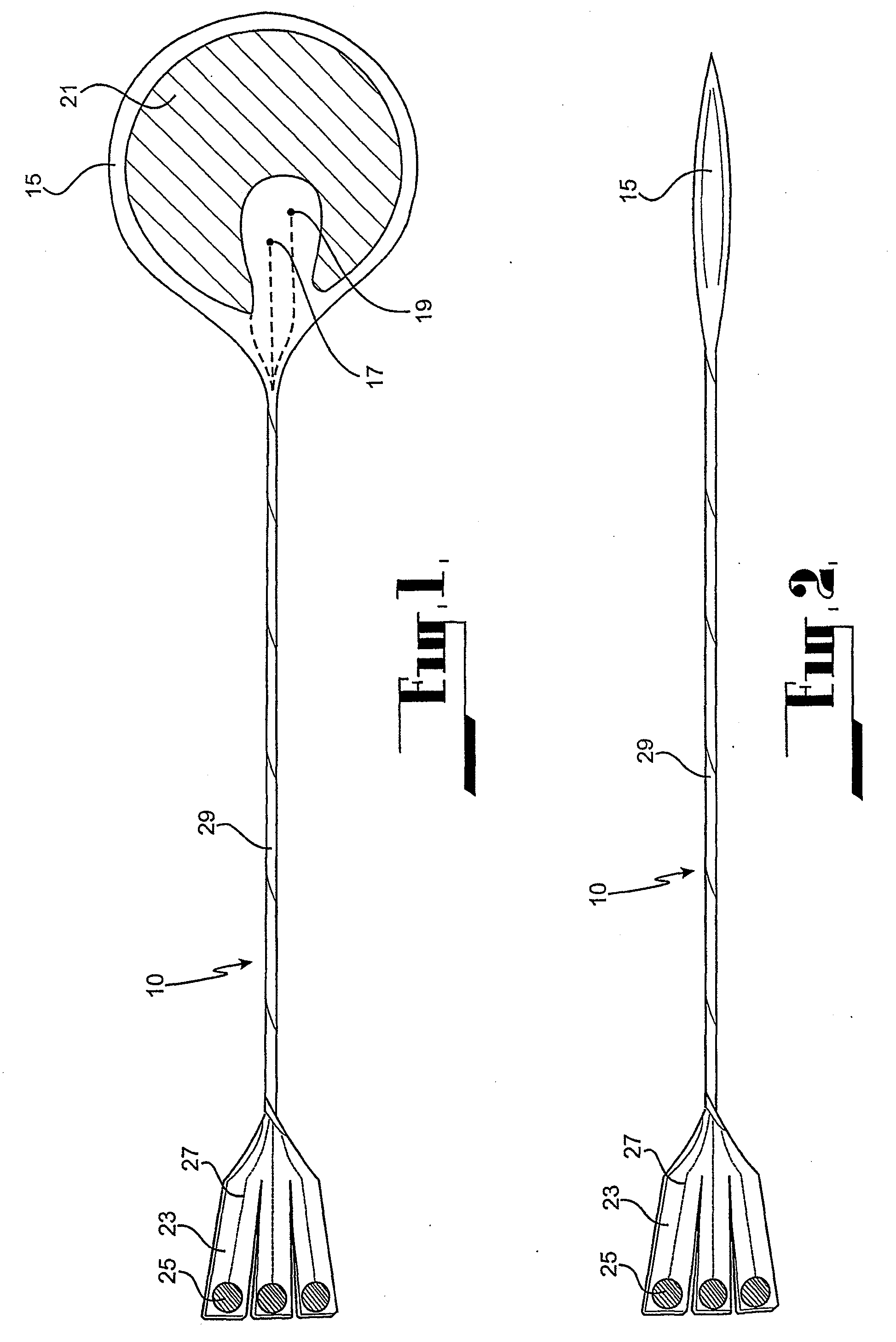
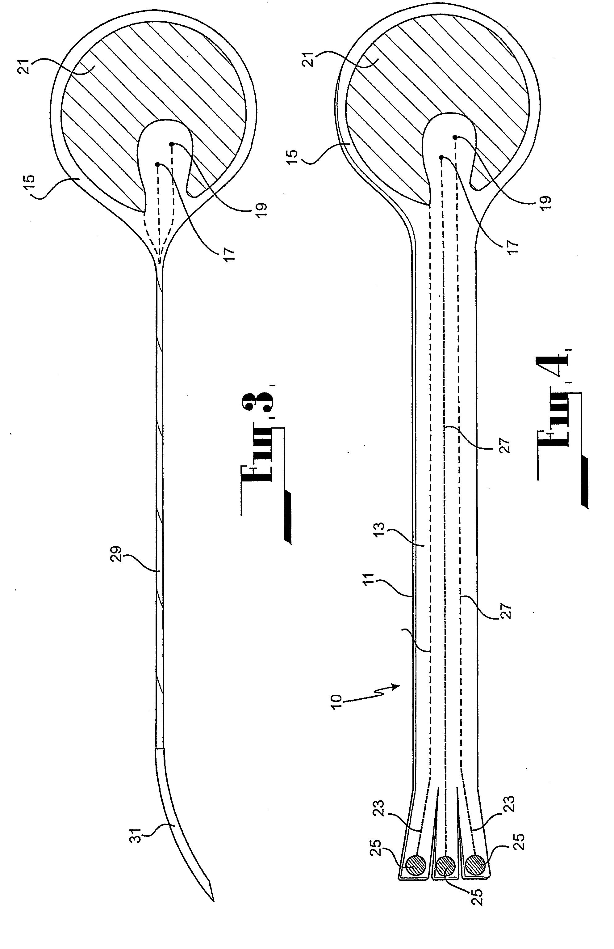
[0081]When the epicardial stimulation lead according to either the first or second embodiment is no longer required in the body of the patient, it is simply pulled out through the chest wall. As the lead is pulled from the patient, the adhesive bond between the wafer and the heart separates and the wafer collapses upon itself as it follows the course of the lead outwardly through the body of the patient 15. The particular benefit of this arrangement is that there is little likelihood of damage to heart tissue as the wafer separates from the heart owing to the fact that it was only affixed to the heart by virtue of the mild adhesive bond.

[0082]The collapsed condition of the wafer is illustrated in FIGS. 2 and 6.

[0083]In the previous embodiments, the stimulation apparatus according to the invention is in the form of a lead, with an electrode or electrode assembly provided at a distal end thereof and the proximal end thereof being adapted to be connected to a source of electrical stimu...

fourth embodiment

[0103]From the foregoing, it is evident that this fourth embodiment provides a simple yet highly effective arrangement for implantation in, and removal of, an epicardial stimulation lead assembly with respect to a body of a cardiac patient.

[0104]It should be appreciated that the invention is not limited to the epicardial stimulation lead assembly according to the embodiments described. The invention may be applied to any biomedical device for transferring electrical impulses to the cardiac system of a person. In addition to cardiac stimulation the invention may possibly have application in cardiac monitoring.


PUM


Abstract

Cardiac stimulation apparatus (10) such as a lead comprising one or more electrodes (17, 19 and 21) for electrical contact with heart or other tissue. An adhesive substance is provided for adhesively attaching the electrodes in position in relation to the heart or other tissue to provide a non-traumatic fixing procedure. The electrodes (17, 19, 21) are positioned on a support (15) to which the adhesive substance is applied attached.

Description

[0001]This application is a Continuation-in-Part of application Ser. No. 10 / 297,189, filed 11 Jul. 2003, and which application(s) are incorporated herein by reference.FIELD OF THE INVENTION[0002]This invention relates to a cardiac stimulation apparatus.BACKGROUND ART[0003]There are occasions where it is necessary to apply electrical stimulation to the hearts of cardiac patients. Typically, electrical stimulation is applied using cardiac stimulation leads. Some cardiac stimulation leads are employed to apply electrical stimulation to the heart of a cardiac patient after surgical procedures to correct arrhythmic beating of the heart. The electrical stimulation may be applied to the atrium, to the ventricle, or sequentially to the atrium and the ventricle of the heart. Other electrical stimulation leads are used to apply electrical stimulation to the heart for the purpose of defibrillation.[0004]Such leads employ an electrode or an electrode assembly at the distal end thereof through w...

Claims


Application Information

Patent Timeline
Patent Type & Authority Applications(United States)
IPC IPC(8): A61N1/00A61B5/04
CPCA61N1/0587
Inventor WILDON, MICHAEL PETER
Owner WILDON MICHAEL PETER
Why Eureka
Try Eureka