Molded rifle stock

a rifle stock and molded technology, applied in the direction of weapons, butts, weapon components, etc., can solve the problems of not addressing the above-discussed problems to the extent possible, rifle stocks generally do not include chambers or cavities, etc., to achieve increased strength and rigidity, good balance, and increase rigidity

a rifle stock and molded technology, applied in the direction of weapons, butts, weapon components, etc., can solve the problems of not addressing the above-discussed problems to the extent possible, rifle stocks generally do not include chambers or cavities, etc., to achieve increased strength and rigidity, good balance, and increase rigidity

US20080244951A1Inactive Publication Date: 2008-10-09SMITH & WESSON

Image

  • Molded rifle stock
  • Molded rifle stock
  • Molded rifle stock

Examples


Embodiment Construction

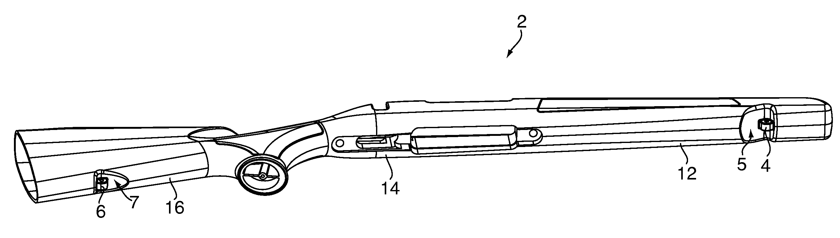
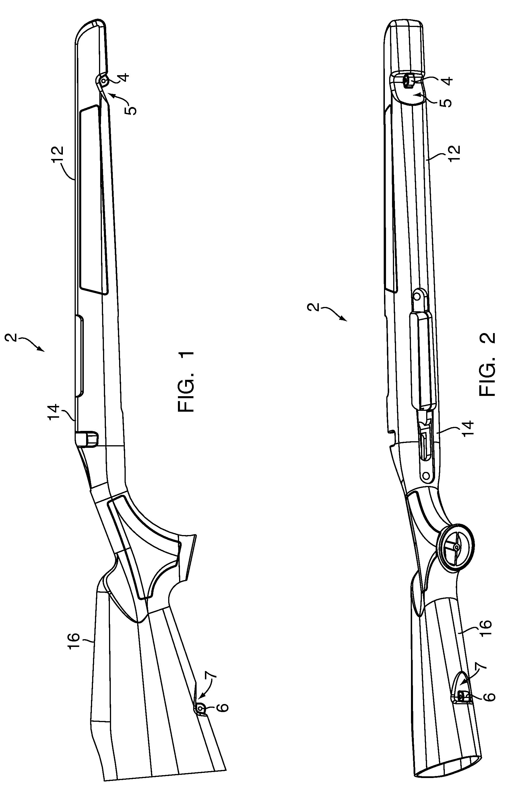
[0032]FIG. 1 depicts a side view of a molded firearm stock 2 made in accordance with an embodiment of the present invention. The stock 2 has a molded front sling lug 4 and a molded rear sling lug 6. The lugs 4 and 6 have an o-shaped opening to accommodate the fastening of a sling (not shown) to the molded firearm stock 2. To attach a sling, a user simply clips the sling via a removable fastener to the o-shaped openings in the molded front sling lug 4 and the molded rear sling lug 6. The lugs 4 and 6 also have clearance portions 5 and 7 molded into the stock 2 adjacent the lugs 4 and 6 to facilitate movement of the sling and sling fastener. The clearance portions 5 and 7 are recesses in the stock 2. By locating the lugs 4 and 6 in the clearance portions 5 and 7, the lugs 4 and 6 do not extend substantially beyond the outer contours of the stock 2.

[0033]The molded lugs 4 and 6 are an important aspect of the present invention since the stock 2 does not have to be drilled to accommodate...


PUM


Abstract

A molded firearm stock is disclosed. The stock includes a molded front sling lug and a molded rear sling lug. Both sling lugs are integrally molded to the stock and accommodate the fastening of a sling. The stock also includes a cavity with an open end that is open to a butt-plate of the stock. The cavity is integrally molded to the stock and is sized to accommodate a recoil-reducing device. The stock has a bed portion with a forward section, and a plurality of crossbeams are in the forward section to provide increased strength and rigidity.

Description

CROSS REFERENCE TO RELATED APPLICATIONS[0001]This application claims the benefit of U.S. Provisional Application Ser. No. 60 / 884,282, filed on Jan. 10, 2007 and U.S. Provisional Application Ser. No. 60 / 943,363 filed on Jun. 12, 2007, herein incorporated by reference in their entirety.FIELD OF THE INVENTION[0002]The present invention relates generally to firearms with a molded stock. The present invention relates more specifically to a molded rifle stock with a molded sling lug and a recoil-reducing cavity. The present invention also relates more specifically to a molded rifle stock bed featuring x-shaped crossbeams that provide increased strength, rigidity and performance.BACKGROUND OF THE INVENTION[0003]Modern rifles are known to have synthetic stocks that are typically manufactured from injection-molded plastic or a molded fiberglass. As will be appreciated, it is important that such stocks be sufficiently strong and rigid to remain straight when being removed from a mold. Moreove...

Claims


Application Information

Patent Timeline
09 Oct 2008
Publication
US20080244951A1
IPC
F41C23/00; F41C23/02
CPC
F41A3/66
Inventors
PICARD, RICHARD A.; SKRUBIS, STEVEN B.