Reversible heat transfer element basket assembly with integrated frame for use in a heat exchanger

a heat exchanger and basket technology, applied in indirect heat exchangers, combustion processes, lighting and heating apparatus, etc., can solve the problems of increasing the cost of the assembly line, introducing the possibility of quality assurance issues associated with the assembly line, and reducing so as to reduce the number of parts, reduce the weight of materials, and reduce the effect of structural integrity loss

Active Publication Date: 2008-10-09
ARVOS LJUNGSTROM LLC
View PDF9 Cites 4 Cited by
  • Summary
  • Abstract
  • Description
  • Claims
  • Application Information

AI Technical Summary

Benefits of technology

[0017]It is also an object of the present invention to provide such a new and improved heat transfer element basket assembly that is characterized by the fact that the material weight of the heat transfer element basket assembly has been reduced without any loss in structural integrity.
[0018]Another object of the present invention is to provide such a new and improved heat transfer element basket assembly that is characterized by its reversibility thereby providing for a maximum life span of the heat transfer element plates, which are supported in the heat transfer element basket assembly, by virtue of enabling the heat transfer element basket assembly to be reversed in its installed position within a rotary regenerative heat exchanger when such reversal of the heat transfer element basket assembly becomes desirable in order to enable both ends of the heat transfer element basket assembly to be exposed equally to the corrosive environment that is known to exist

Problems solved by technology

Although such prior art forms of heat transfer element basket assemblies are still commonly found in use, such prior art forms of heat transfer element basket assemblies are typically subject to rotational torsion of the side straps that are utilized therein as well as to lateral deformation due to the bowing of such side straps, which are employed therein to interconnect the spaced end plates thereof.
Further to this point, such hand welding during fabrication requires not only that there be extra time allotted for purposes of effecting the fit up of the welding fixtures that are need

Method used


Image

  • Reversible heat transfer element basket assembly with integrated frame for use in a heat exchanger
  • Reversible heat transfer element basket assembly with integrated frame for use in a heat exchanger
  • Reversible heat transfer element basket assembly with integrated frame for use in a heat exchanger

Examples


Embodiment Construction

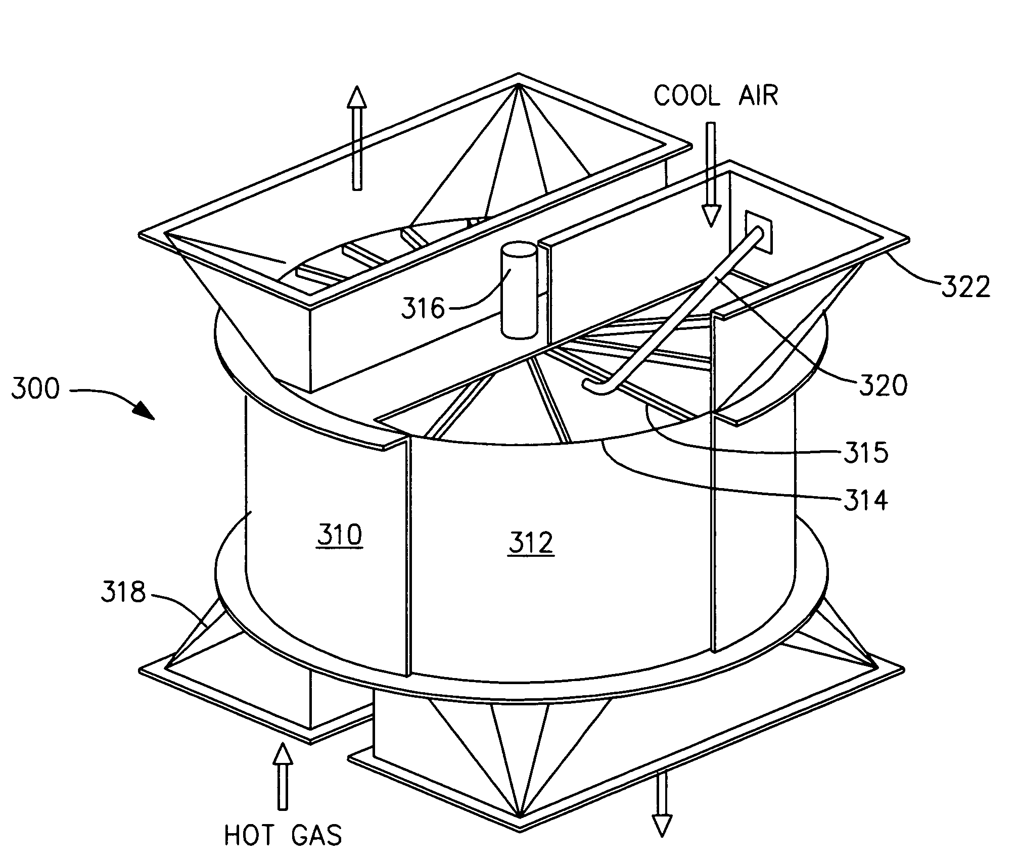
[0041]Referring to FIG. 3 of the drawings, there is depicted therein a rotary regenerative heat exchanger 300 in which a heat transfer element basket assembly constructed in accordance with the present invention is capable of being utilized. The heat transfer element basket assembly constructed in accordance with the present invention may also be deemed to constitute a heat transfer element basket frame. As illustrated in FIG. 3 of the drawings, the rotary regenerative heat exchanger 300 includes a housing 310 within which there is enclosed a rotor 312 in turn within which a heat transfer element basket assembly constructed in accordance with the present invention is designed to be suitably supported. The rotor 312 is in the form of a cylindrical shell 314, which is suitably connected, as best understood with reference to FIG. 3 of the drawings, by means of radially extending diaphragms 315 to a rotor post 316. A hot fluid is made to enter the housing 310 through the duct 318 wherea...


PUM


Abstract

A heat exchanger heat transfer element basket assembly (500) for receiving heat transfer element plates (850) therein. The heat exchanger heat transfer element basket assembly (500) includes first and second one-piece side straps (520a, 520b), a pair of inboard corner flanges (528a, 528b), an I-shaped splitter plate (530), a pair of outboard corner flanges (522a, 522b), first and second end straps (526a, 526b), and a cap. Each of the first and second one-piece side straps (520a, 520b) includes a center portion (625), a first extension (630), and a second extension (635). Each of the first and second extensions (630, 635) includes a flange portion that is folded over across the heat transfer element plates (850) so as to be operative to retain the heat transfer element plates (850) in the heat exchanger heat transfer element basket assembly (500).

Description

FIELD OF THE INVENTION[0001]The present invention relates to a rotary regenerative heat exchanger, and more particularly, to an improved low profile heat transfer element basket assembly for use in such a heat exchanger.BACKGROUND OF THE INVENTION[0002]The present invention has particular application in a heat transfer apparatus in which the heat transfer element, also called a sheet or plate, is heated by contact with a hot gaseous heat exchange fluid and is thereafter brought in contact with preferably a cool gaseous heat exchange fluid to which the heat transfer element gives up the heat that the heat transfer element has received by virtue of the heat transfer element's contact with the aforementioned hot gaseous heat exchange fluid.[0003]One type of such heat exchange apparatus, which is commonly found in use, is that which those in the industry refer to as a rotary regenerative heat exchanger. Typically, such a rotary regenerative heat exchanger includes a cylindrical rotor th...

Claims


Application Information

Patent Timeline
IPC IPC(8): F28D11/02
CPCF28D19/044F28D19/04F28D11/02
Inventor CHILDS, CARY J.COWBURN, LAWRENCE G.GAYLOR, JEFFREY W.GIBBLE, MARK M.GUSTIN, TIMOTHY R.PYE, DAVID A.RHODES, DEAN L.
Owner ARVOS LJUNGSTROM LLC
Why Eureka
Try Eureka