Structure of coaxial-to-waveguide transition and traveling wave tube

a technology of coaxial-to-waveguide transition and traveling wave tube, which is applied in the direction of travelling-wave tube, electric discharge tube, electrical apparatus, etc., can solve the problems of complex operation of adjusting impedance and increase manufacturing costs, and achieve the effect of easy adjustment of the impedance of the structure of the coaxial-to-waveguide transition

Active Publication Date: 2008-10-09
NEC NETWORK & SENSOR SYST
View PDF2 Cites 14 Cited by
  • Summary
  • Abstract
  • Description
  • Claims
  • Application Information

AI Technical Summary

Benefits of technology

[0010]An object of the present invention is to provide a structure of a coaxial-to-waveguide that is transition capable of easily adjusting the characteristic impedance by a coaxial center conductor of exterior portion, and a traveling wave tube.
[0012]The structure of the coaxial-to-waveguide transition according to the present invention configured as above moves the end of the coaxial center conductor of the exterior portion in the axial direction of the coaxial center conductor of the exterior portion by the screw part, and thereby, impedance is easily adjusted by the coaxial center conductor of the exterior portion.
[0017]Further, the screw part included in the structure of the coaxial-to-waveguide transition according to the present invention preferably includes a screw member supporting the coaxial center conductor of the exterior portion, a screw hole which is formed in the waveguide and provided so that the screw member is movable, and a restriction part restricting the movement of the screw member so that the screw member is moved only in the inside of the screw hole. According to this configuration, the screw member which is moved inside the screw hole is restricted in movement in the axial direction of the screw member by the restriction part, and therefore, the screw member is not projected to the inside of the waveguide. Therefore, unintended change in impedance by the screw member is prevented, and the occurrence of arcing in the tip end portion of the screw thread inside the waveguide is prevented.
[0018]Further, in the coaxial connection part of the structure of the coaxial-to-waveguide transition according to the present invention, a dielectric for adjusting impedance in the coaxial connection part may be provided at a position adjacent to the insulating and sealing member. According to this configuration, the impedance in the vicinity of the insulating and sealing member is varied to a relatively large extent, and therefore, the structure of the coaxial-to-waveguide transition can be easily applied to the other specifications that have different impedances.
[0020]According to the present invention, the coaxial center conductor of the exterior portion is supported by turning of the screw part provided in the waveguide to be movable in its axial direction, and the coaxial center conductor of the exterior part is moved in its axial direction by adjustment by the screw part, whereby impedance of the structure of the coaxial-to-waveguide transition can be easily adjusted.

Problems solved by technology

Therefore, there are disadvantages in that the operation of adjusting impedance is complicated, and manufacturing costs increase.

Method used


Image

  • Structure of coaxial-to-waveguide transition and traveling wave tube
  • Structure of coaxial-to-waveguide transition and traveling wave tube
  • Structure of coaxial-to-waveguide transition and traveling wave tube

Examples


first exemplary embodiment

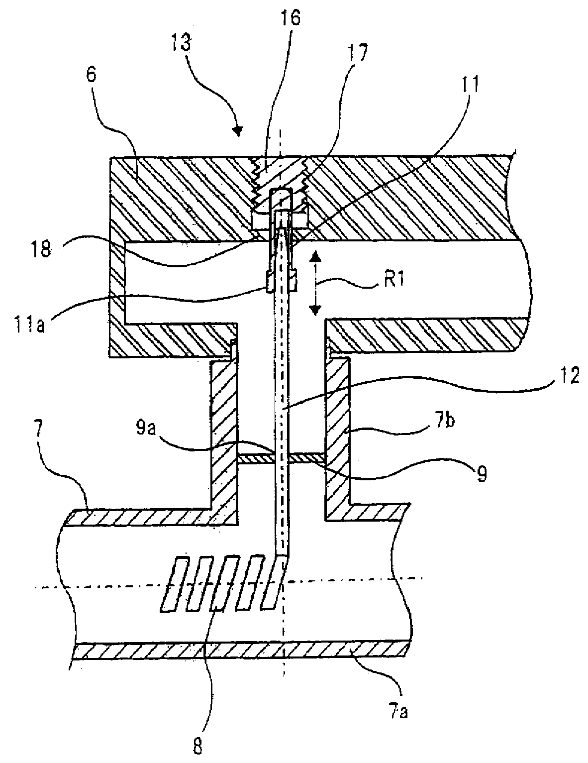
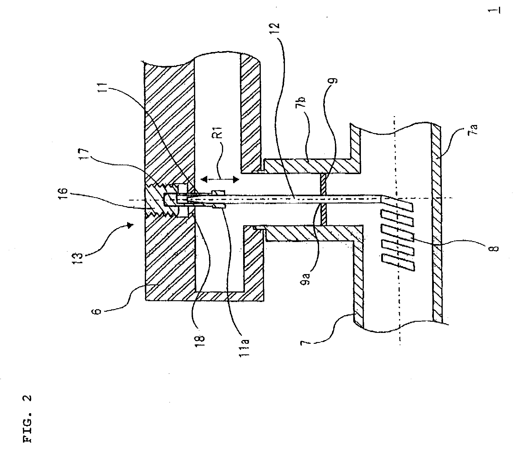
[0028]In order to output amplified radio frequency signals, a traveling wave tube includes output transition section 1 as shown in FIG. 2. As shown in FIGS. 2 and 3, output transition section 1 of a first exemplary embodiment includes waveguide 6 for outputting radio frequency signals, vacuum envelope 7 provided with slow-wave circuit 8 in the interior of the vacuum, insulating window member (insulating and sealing member) 9 which hermetically seals a side of vacuum envelope 7 and a side of waveguide 6, coaxial center conductor of exterior portion 11 with one end supported by waveguide 6, and coaxial center conductor of interior portion 12 with one end abutting on slow-wave circuit 8 and the other end connected to coaxial center conductor of exterior portion 11.

[0029]Waveguide 6 of output transition section 1 is formed by a metal material, and is provided with connection hole 6a to which coaxial connection part 7b of vacuum envelope 7, which will be described later, is connected, as...

second exemplary embodiment

[0045]As shown in FIG. 4, output transition section 2 of a second exemplary embodiment includes the coaxial center conductor of exterior portion 26 with one end supported by waveguide 6, and the coaxial center conductor of interior portion 27 with one end abutting on slow-wave circuit 8 and the other end connected to the coaxial center conductor of exterior portion 26.

[0046]The coaxial center conductor of exterior portion 26 is formed to have a predetermined length so that when it is moved in the axial direction of the coaxial center conductor of exterior portion 26 by screw part 131 end portion 26a formed to have a large outside diameter is displaced within moving range R2 in the inside of coaxial connection part 7b of vacuum envelope 7. The coaxial center conductor of interior portion 27 is formed to have a predetermined length corresponding to the length of the coaxial center conductor of exterior portion 26.

[0047]In output transition section 2 configured as above, the position o...

third exemplary embodiment

[0049]As shown in FIG. 5, in addition to the configuration of the second exemplary embodiment, output transition section 3 of a third exemplary embodiment includes dielectric 28 for varying impedance in the vicinity of insulating window member 9 inside coaxial connection part 7b of vacuum envelope 7 to a relatively large extent, that is, for shifting the impedance.

[0050]Dielectric 28 is formed into a disk shape by a dielectric material such as, for example, polytetrafluoroethylene, and is disposed at the position adjacent to insulating window member 9. Insertion hole 28a through which coaxial center conductor of interior portion 27 is inserted is provided in a central portion of dielectric 28.

[0051]According to output transition section 3 of this exemplary embodiment, by properly changing the outside dimension such as thickness and the material of dielectric 28 when necessary, the impedance is shifted to a relatively large extent, and output transition section 3 can be easily applie...


PUM


Abstract

The present invention includes a waveguide for outputting radio frequency wave, a vacuum envelope provided with a slow-wave circuit, a coaxial connection part connecting the waveguide and the vacuum envelope, an insulating window member which is provided in the coaxial connection part and which hermetically seals a said of vacuum envelope and a said of waveguide, a coaxial center conductor of exterior portion with one end supported by the waveguide, and a coaxial center conductor of an interior portion with one end abutting on the slow-wave circuit and the other end connected to the coaxial center conductor of the exterior portion. The waveguide is provided with a screw part supporting the coaxial center conductor of the exterior portion movably in an axial direction of the coaxial center conductor of the exterior portion. An end portion of the coaxial center conductor of the exterior portion is connected to the end portion of the coaxial center conductor of the interior portion movably in the axial direction of the coaxial center conductor of the exterior portion.

Description

[0001]This application is based upon and claims the benefit of priority from Japanese Patent Application No. 2007-101713 filed on Apr. 9, 2007, the content of which is incorporated by reference.BACKGROUND OF THE INVENTION[0002]1. Field of the Invention[0003]The present invention relates to a structure of a coaxial-to-waveguide transition for an input and / or output of radio frequency signals, and a traveling wave tube including the structure of the coaxial-to-waveguide transition.[0004]2. Description of the Related Art[0005]Conventionally, a traveling wave tube is known as a microwave tube.[0006]Many traveling wave tubes include structures of coaxial-to-waveguides transition as input window in which a radio frequency wave is inputted, or output window from which a radio frequency wave is outputted.[0007]The output window included in a traveling wave tube related to the present invention is disclosed, for example, in Japanese Utility Model Laid-Open No. 5-23397 (see FIG. 1). As shown ...

Claims


Application Information

Patent Timeline
Patent Type & Authority Applications(United States)
IPC IPC(8): H01P5/103
CPCH01P5/103
Inventor OKAMOTO, KOJI
Owner NEC NETWORK & SENSOR SYST
Why Eureka
Try Eureka