Dc/dc converter

Inactive Publication Date: 2008-10-09
TDK CORPARATION
View PDF5 Cites 26 Cited by
  • Summary
  • Abstract
  • Description
  • Claims
  • Application Information

AI Technical Summary

Benefits of technology

[0014]In the secondary side coils there is induced normally current having an opposite orientation to that of the primary side coils. Therefore, the influence of the skin effect and the proximity effect diminishes, and AC resistance decreases, when the secondary side coils are adjacent. Thus, the AC resistance of the primary side coils can be increased by arresting the output current of the secondary side coils adjacent to the primary side coils, on the basis of, for instance, the reverse breakdown voltage of diodes.
[0015]Connecting in series, as des

Problems solved by technology

When plural transformers are operated in parallel and there is variation in the output of inverter circuits connected to the respective transformers, there oc

Method used


Image

  • Dc/dc converter
  • Dc/dc converter
  • Dc/dc converter

Examples


Example

[0052]A DC / DC converter according to an embodiment is explained as an example of a switching supply. Identical elements are denoted with identical reference numerals, and recurrent explanations thereof are omitted.

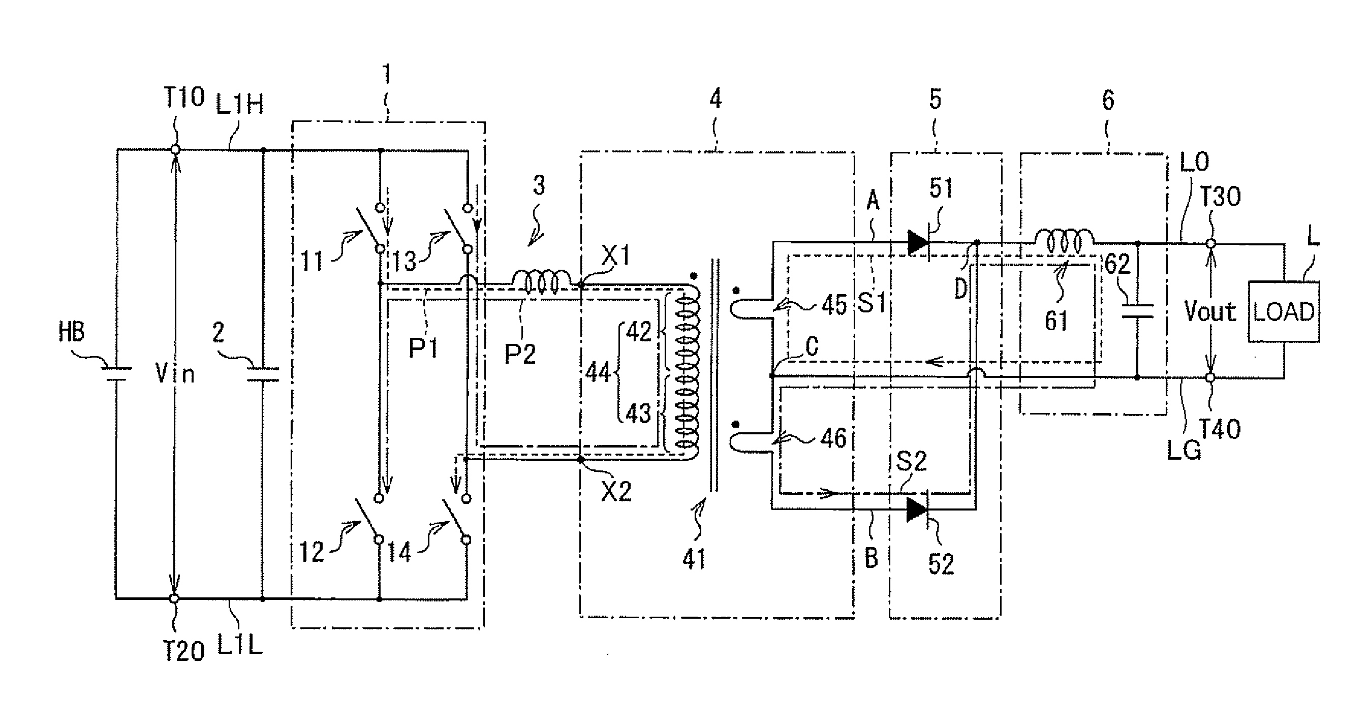
[0053]FIG. 1 is a circuit diagram of a DC / DC converter.

[0054]In the DC / DC converter, the output side of a first transformer GA and a second transformer GB are connected in parallel, such that there can be obtained an amount of current that is twice that of each transformer. The first transformer GA has an upper-stage coil group area G1 and a lower-stage coil group area G3. The second transformer GB has an upper-stage coil group area G2 and a lower-stage coil group area G4. The coil group areas G1, G2, G3 and G4 comprise each at least one pair of coil pairs, such coil pairs comprising each a primary side coil and a secondary side coil magnetically coupled.

[0055]A primary side coil 42 of the upper-stage coil group area G1 of the first transformer GA is connected in series wi...


PUM


Abstract

According to the switching supply such as a DC/DC converter, since primary side coils provided in two transformers are mutually connected in series, voltage variation generated in parallel-connected secondary side coils can be suppressed, and the uniformity of secondary side parallel output can be enhanced even in case of voltage value fluctuations or the like caused by variation in the output of an inverter circuit.

Description

BACKGROUND OF THE INVENTION[0001]1. Field of the Invention[0002]The present invention relates to a switching supply such as a DC / DC converter or the like comprising a plurality of connected transformers.[0003]2. Related Background Art[0004]A conventional switching supply such as a DC / DC converter is disclosed in, for instance, Japanese Patent No. 2,629,999. The DC / DC converter disclosed in Japanese Patent No. 2,629,999 comprises two connected output transformers. In a first output transformer, two primary side coils are arranged along the same magnetic path and with the same polarity. One primary side coil in the first output transformer and one primary side coil in the second output transformer are switched by a first driving circuit, while another primary side coil in the first output transformer and another primary side coil in the second output transformer are switched by a second driving circuit, to stabilize thereby the DC / DC converter. Secondary side coils of the transformers...

Claims


Application Information

Patent Timeline
IPC IPC(8): H02M3/335
CPCH01F27/2847H01F27/343H01F27/42H01F2027/2819H02M3/337H02M7/003H02M3/33573H02M3/01H02M3/33571
Inventor NAKAHORI, WATARU
Owner TDK CORPARATION
Why Eureka
Try Eureka