Position determination system using radio and laser in combination

a technology of laser and positioning system, applied in direction finders using radio waves, navigation instruments, instruments, etc., can solve the problem of inherently poor vertical geometry of prior art ground based positioning system, and achieve the effect of improving the vertical positioning capability of such system

Active Publication Date: 2008-10-09
TRIMBLE NAVIGATION LTD
View PDF9 Cites 27 Cited by
  • Summary
  • Abstract
  • Description
  • Claims
  • Application Information

AI Technical Summary

Benefits of technology

[0005]The present invention addresses this problem by augmenting the ground based radio positioning system wit

Problems solved by technology

However, the prior art ground based positioning

Method used


Image

  • Position determination system using radio and laser in combination
  • Position determination system using radio and laser in combination
  • Position determination system using radio and laser in combination

Examples


example i

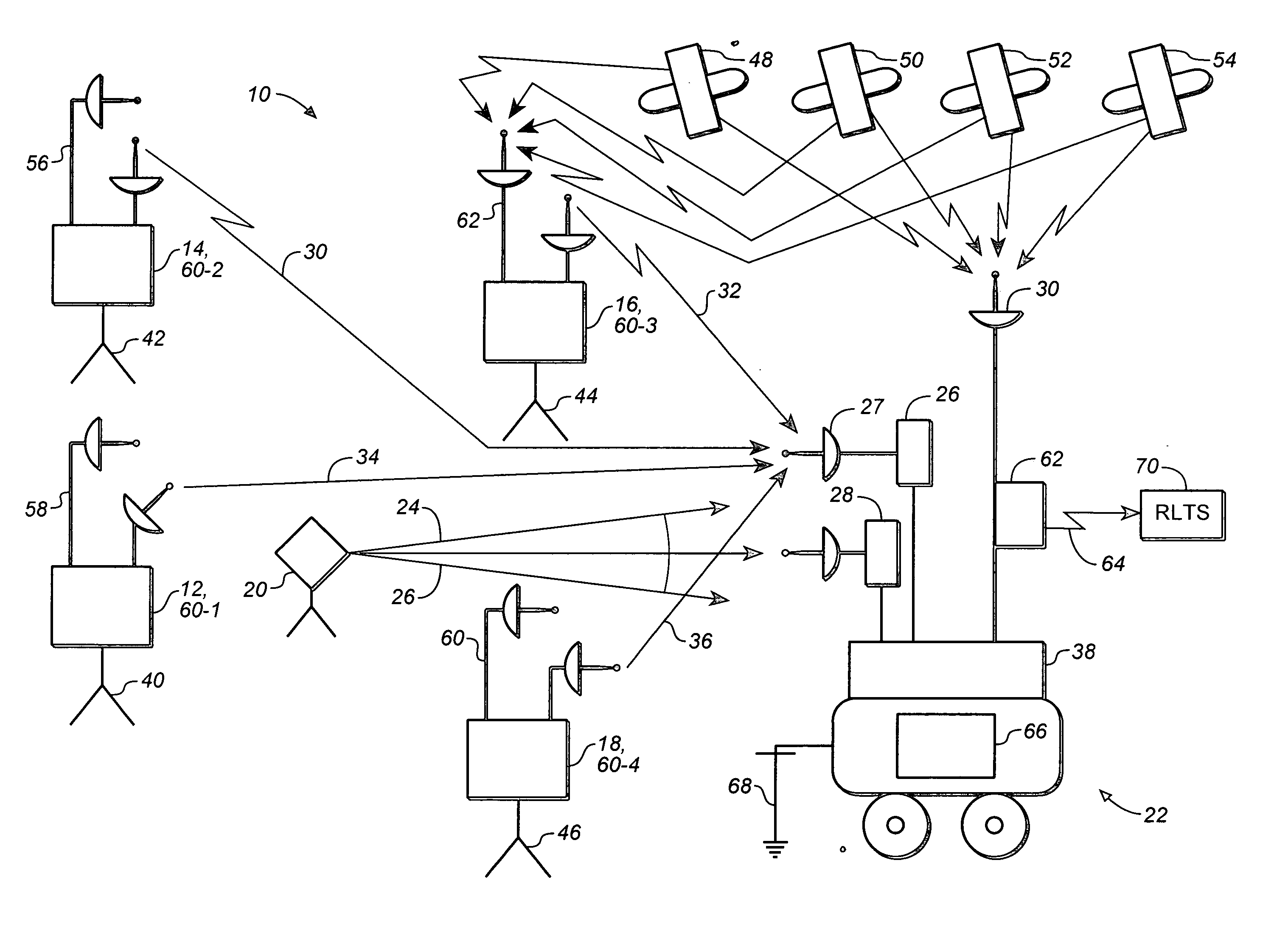
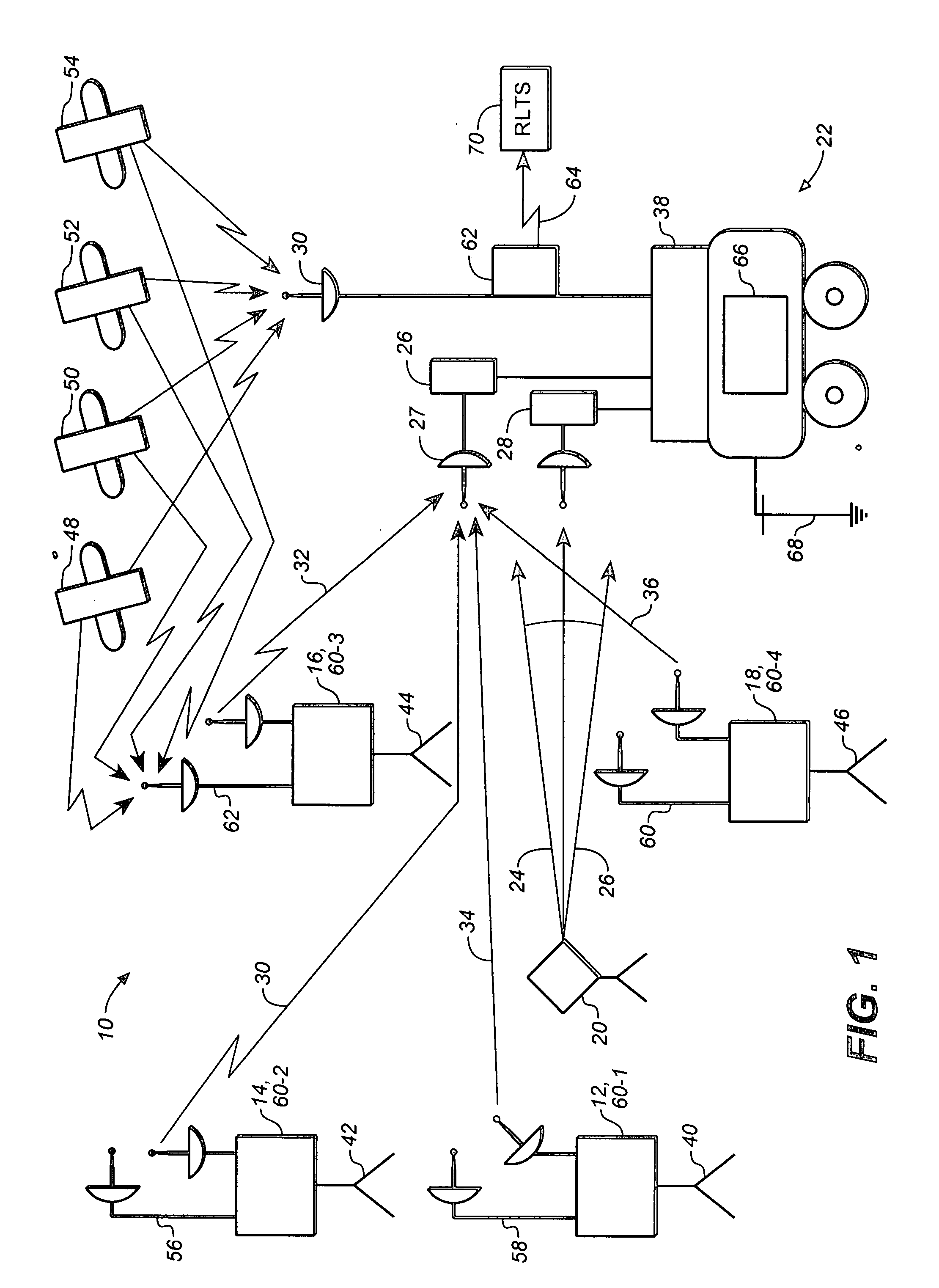
[0046]The ground based radio communication device 12 further comprises a ground based radio transceiver placed in a location 40 with known coordinates, the ground based radio communication device 14 further comprises a ground based radio transceiver placed in a location 42 with known coordinates, the ground based radio communication device 16 further comprises a ground based radio transceiver placed in a location 44 with known coordinates, and the ground based radio communication device 18 further comprises a ground based radio transceiver placed in a location 46 with known coordinates.

[0047]In one embodiment of the present invention, at least one ground based radio communication device (12, 14, 16, and / or 18) further comprises a stationary radio positioning system (RADPS) receiver (58, 56, 62, and 60 respectively) integrated with a ground based radio transmitter, wherein position coordinates of a ground based radio transmitter are determined by using a plurality of radio signals t...

example ii

[0076]It is sufficient to have four synchronized ground based radio transceivers to provide 3-D solution for position coordinates of each mobile unit because it takes three equations to obtain 3-D position coordinates of each mobile unit plus one equation for synchronization of timing coordinate.

[0077]In one embodiment of the present invention, the network of ground based radio communication devices of FIG. 1 (12, 14, 16, and 18) further comprises at least four synchronized ground based radio transceivers having a substantially weak vertical geometry. In this embodiment of the present invention, the network of at least four synchronized ground based radio transceivers provides 3-D solution for position coordinates of each mobile unit 22, wherein the 3-D solution has a substantially low vertical accuracy.

example iii

[0078]Four synchronized ground based radio transceivers have a substantially weak vertical geometry will provide 3-D solution for position coordinates of each mobile unit also having a substantially weak vertical geometry because the vertical (Z) coordinate will be over determined.

[0079]Referring still to FIG. 1, in one embodiment of the present invention, the network of ground based radio communication devices further comprises at least three synchronized ground based radio transceivers 12, 14, and 16. In this embodiment of the present invention, the network of at least three synchronized ground based radio transceivers provides 2-D solution for horizontal position coordinates of each mobile unit 22.


PUM


Abstract

A combined radio and laser positioning system comprising: a network of ground based radio communication devices, a laser transmitter configured to generate at least one laser beam, and at least one user unit. Each user unit comprises a radio receiver configured to receive at least one ranging radio signal transmitted by at least one ground based radio communication device, a laser detector configured to receive at least one laser beam generated by the laser transmitter, and a processor configured to convert a set of data including: {a set of data transmitted by at least one ranging radio signal, and a set of data transmitted by said at least one laser beam} into position coordinates of the user unit, wherein a set of vertical coordinates of the user unit is obtained with a laser-assisted (LA) accuracy.

Description

BACKGROUND OF THE INVENTION[0001]1. Field of the Invention[0002]The current invention relates to position tracking and machine control systems, and, more specifically, to a combination of laser systems and ground based radio positioning systems.[0003]2. Discussion of the Prior Art[0004]The prior art ground based positioning system can provide a plurality of mobile units with positioning data. However, the prior art ground based positioning system have inherently poor vertical geometry.SUMMARY OF THE INVENTION[0005]The present invention addresses this problem by augmenting the ground based radio positioning system with a laser transmitter to improve the vertical positioning capability of such system up to millimeter accuracy.[0006]More specifically, one aspect of the present invention is directed to a combined radio and laser positioning system.[0007]In one embodiment, the positioning system of the present invention comprises: a network of ground based radio communication devices, a ...

Claims


Application Information

Patent Timeline
IPC IPC(8): H04B10/00
CPCG01S5/16G01S19/11G01S19/12G01S19/46
Inventor NICHOLS, MARK E.
Owner TRIMBLE NAVIGATION LTD
Why Eureka
Try Eureka