Liquid transfer device and suction unit

a technology of liquid transfer device and suction unit, which is applied in the direction of positive displacement liquid engine, machine/engine, bend, etc., can solve the problem that the tube may suffer permanent deformation

Inactive Publication Date: 2008-10-09
SEIKO EPSON CORP
View PDF6 Cites 51 Cited by
  • Summary
  • Abstract
  • Description
  • Claims
  • Application Information

AI Technical Summary

Benefits of technology

[0051]With such a configuration in which the upper and lower frames can be separated, consumable items such as power supply section, i.e., small-sized battery, and reservers can be replaced with ease.

Problems solved by technology

The problem here is that the tube pump of such a configuration has only one tube available for liquid transfer.
Accordingly, there may be a possibility that the tubes may suffer from permanent deformation if the tubes remain depressed for a long time.

Method used


Image

  • Liquid transfer device and suction unit
  • Liquid transfer device and suction unit
  • Liquid transfer device and suction unit

Examples


first embodiment

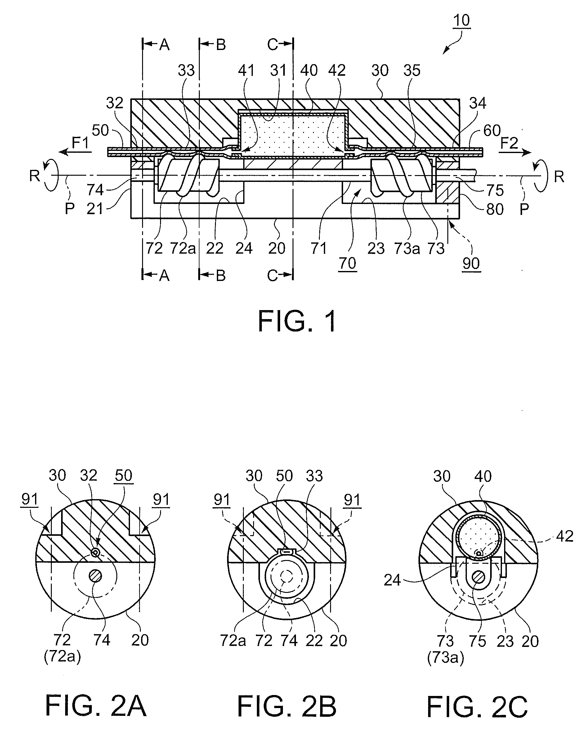
[0067]FIG. 1 is a vertical cross sectional view of a liquid transfer device of a first embodiment, and FIGS. 2A to 2C are horizontal cross sectional views of the liquid transfer device of FIG. 1, i.e., FIG. 2A is a cross sectional view of the device along a line A-A, FIG. 2B is a cross sectional view of FIG. 2A along a line B-B, and FIG. 2C is a cross sectional view of FIG. 2A along a line C-C. In FIGS. 1 to 2C, a liquid transfer device 10 is configured to include a reserver 40 storing therein a liquid, first and second tubes 50 and 60, and a tube depressing member 70. The first tube 50 is made elastic, and is extended in one direction after being linked to the reserver 40. The second tube 60 is also made elastic, and is extended in a direction opposite to that of the first tube 50 after being linked to the reserver 40. The tube depressing member 70 is provided for depressing both the first and second tubes 50 and 60.

[0068]As shown in FIG. 1, at the lower portion of the reserver 40,...

second embodiment

Modified Example of Second Embodiment

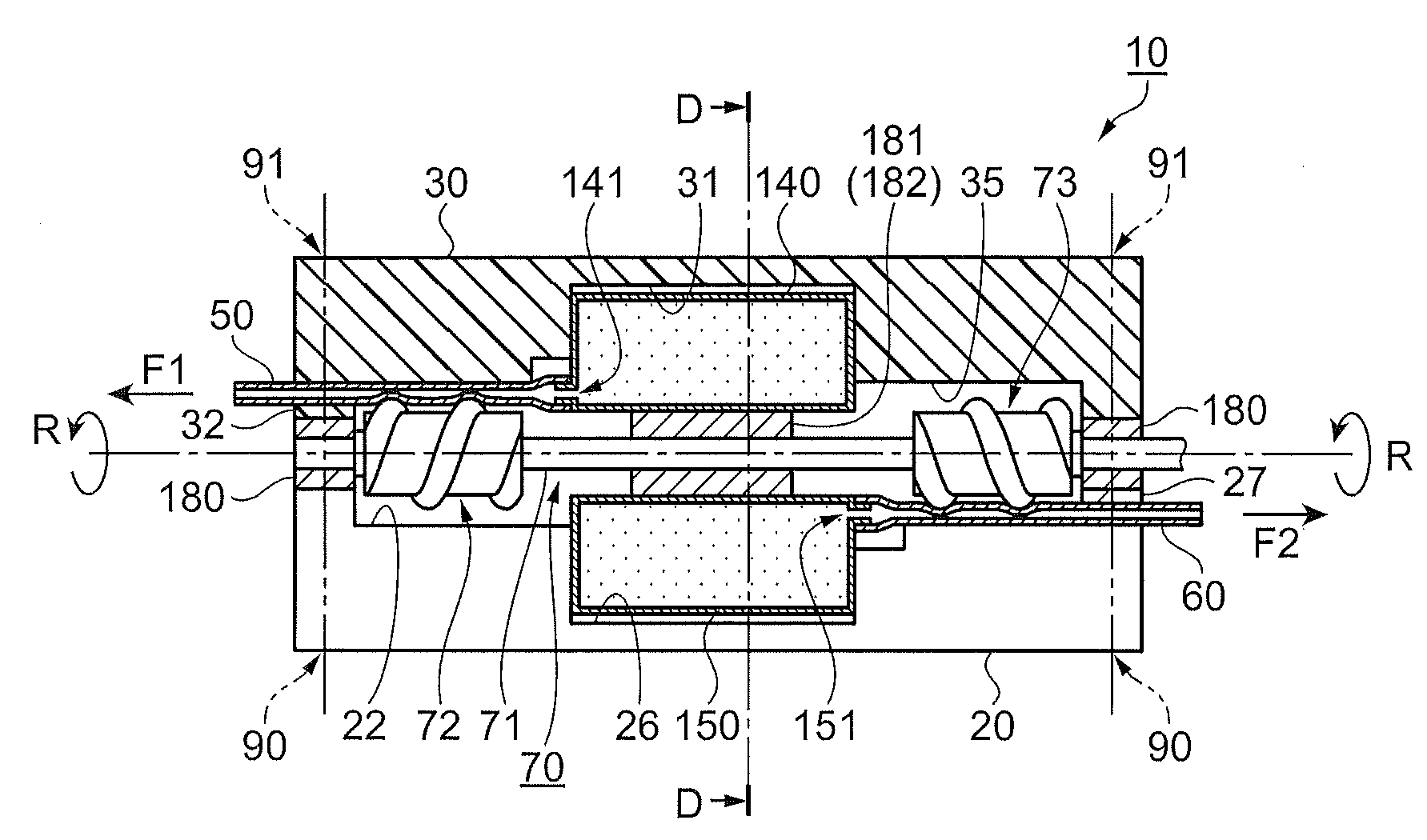
[0102]Described next is a modified example of the second embodiment by referring to the accompanying drawings. Compared with the second embodiment described above, this modified example is characterized in that the first and second reservers 140 and 150 are disposed around the rotation axis P, i.e., the tube depressing member 70. Therefore, any component similar to that of the second embodiment is provided with the same reference numeral, and any difference from the second embodiment is mainly described.

[0103]FIGS. 4A and 4B are each a diagram showing a liquid transfer device in the modified example of the second embodiment, i.e., FIG. 4A is a cross sectional view of the liquid transfer device when viewed from the above, and FIG. 4B is a cross sectional view of FIG. 4A along a line D-D. In FIGS. 4A and 4B, the second reserver 150 is disposed on the side opposite to the first reserver 140 with the tube depressing member 70 disposed therebetween. A...

third embodiment

[0114]Next, a liquid transfer device of a third embodiment is described by referring to the accompanying drawings. The third embodiment is characterized in the configuration of a tube depressing member, and any remaining components are structurally adaptable to those in the first and second embodiments described above. A description is thus given about the tube depressing member by referring to the drawing.

[0115]FIG. 5 is a front view of a tube depressing member of the third embodiment. In FIG. 5, a tube depressing member 170 is configured to include first and second depressing sections 172 and 173, a coupling shaft 171, and support shafts 176 and 177. The coupling shaft 171 serves to couple together the first and second depressing sections 172 and 173, and the support shafts 176 and 177 are respectively provided to end portions of the tube depressing member 170.

[0116]Note here that these components, i.e., the first and second depressing sections 172 and 173, the coupling shaft 171,...


PUM


Abstract

A liquid transfer device that includes: a plurality of reservers that each store therein a liquid; a plurality of elastic tubes that are linked to the reservers and retained by a tube guide; a rotation axis that is retained to be able to rotate; and a tube depressing member whose depressing section is fixed to the rotation axis for depressing the tubes with a helical-structured convex portion provided thereto. In the liquid transfer device, when the rotation axis rotates, the liquid starts to flow by the depressing section sequentially depressing the tubes in a direction from the reservers toward a flow-out side of the liquid.

Description

BACKGROUND[0001]1. Technical Field[0002]The present invention relates to a liquid transfer device that transfers a liquid in one or two different directions by depressing a plurality of tubes using a tube depressing member formed with a helical-shaped convex portion, and a suction unit including the liquid transfer device and an atomizer.[0003]2. Related Art[0004]There has been known a tube pump (liquid transfer device) that includes a helical roller configured by a rotation axis disposed in parallel with a tube and a helical-structured convex portion formed on the rotation axis and operates to rotate the helical roller and depress the tube by the helical-structured convex portion, whereby a liquid is flowed (e.g., JP-A-2003-301778; p.p. 5 and 6, and FIG. 2).[0005]The tube pump of JP-A-2003-301778 is of a configuration that the tube is depressed by the helical-structured convex portion formed on the rotation axis. The helical roller is thus implemented by such a simple configuration...

Claims


Application Information

Patent Timeline
Patent Type & Authority Applications(United States)
IPC IPC(8): F04B43/12F04F10/00
CPCF04B43/12F04B43/1223Y10T137/2897
Inventor KAWASUMI, KAZUO
Owner SEIKO EPSON CORP
Why Eureka
Try Eureka