Magnetic drapery track

a magnetic drapery and track technology, applied in the field of magnetic drapery track, can solve the problems of damage to drywall/plasterboard (gypsum), cumbersome installation of mounting hardware, and difficulty in repairing drywall/plasterboard

Active Publication Date: 2008-10-16
HOME DEV OF CLEARWATER CORP
View PDF24 Cites 4 Cited by
  • Summary
  • Abstract
  • Description
  • Claims
  • Application Information

AI Technical Summary

Benefits of technology

[0007]This invention relates to a drapery track. It relates to an improved drapery track utilizing a plurality of magnets each having opposed flat surfaces defining north and South Pole along a said channel thereby eliminating the need for mounting hardware (

Problems solved by technology

Mounting hardware is often cumbersome to install because the hardware is so small.
Installing the mounting hardware often requires numer

Method used


Image

  • Magnetic drapery track
  • Magnetic drapery track
  • Magnetic drapery track

Examples


Embodiment Construction

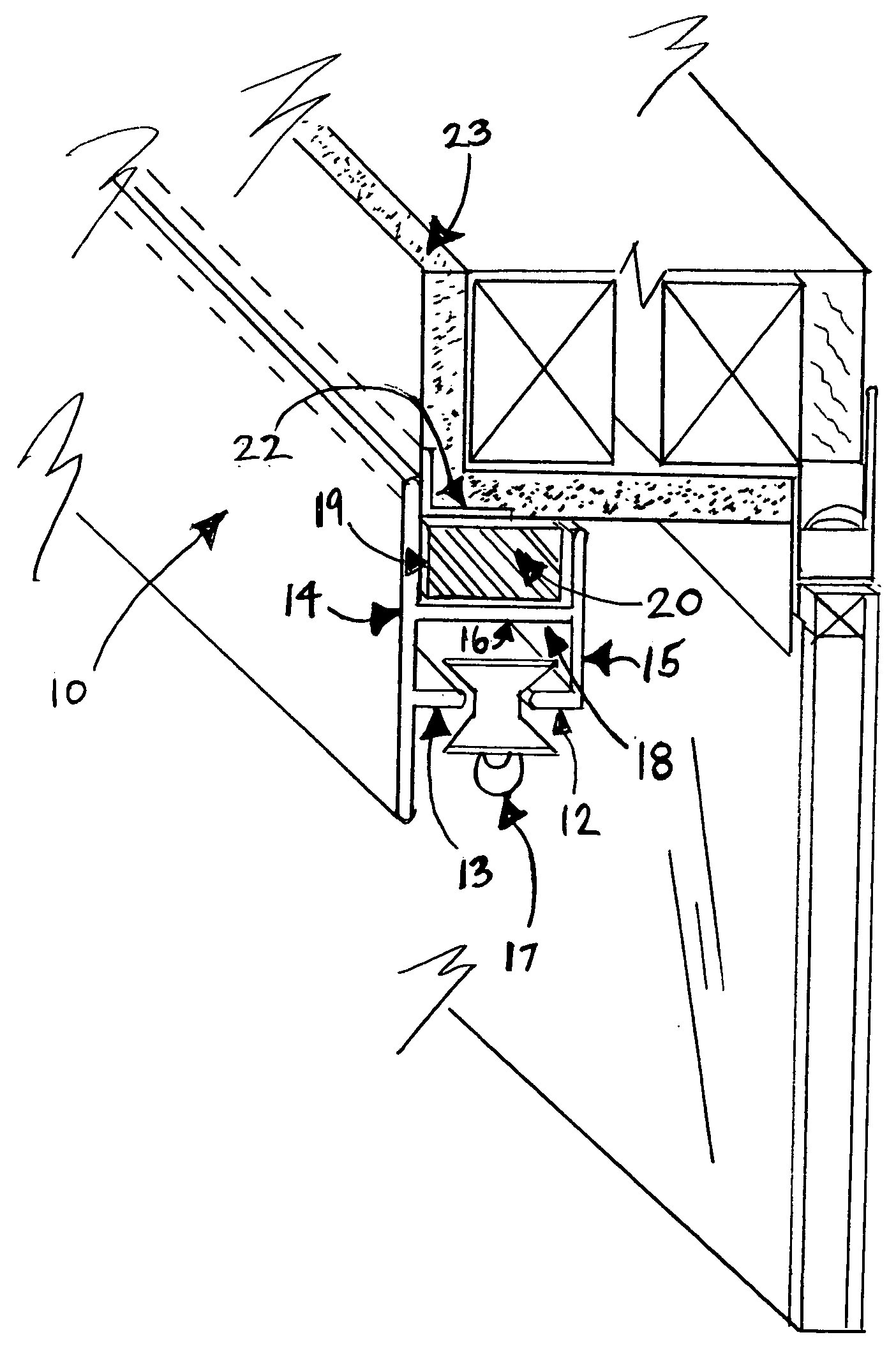
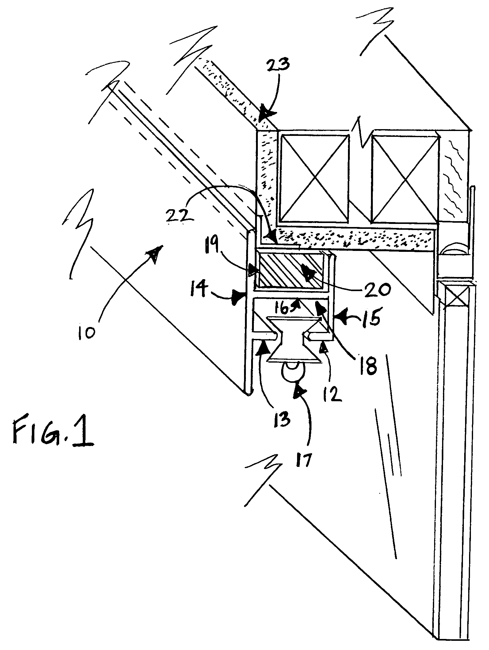
[0012]Referring to FIG. 1, a magnetic drapery track without mounting hardware 10 is formed as an elongated aluminum extrusion or extruded thermoplastic track which has infinite lengths. The track 10 is generally a rectangular cross-sectional configuration and includes at least two channel formations 18, 19. The drapery carrier members are of many types 17 being illustrated. Carrier members 17 slide within said track 10 along flanges 12, 13 to receive supporting fasteners and also run the gamut. These fasteners attach to the heading hem of a drapery panel and can include fabrics and or materials of different weights. FIG. 1 illustrates two channel formations 18, 19 extending the length of track 10. The channels 18, 19 are defined by parallel facing sidewalls 14, 15. Each adjacent sidewall 14 and 15 is formed with right angle flanges 12, 13 along channel 18. Where carrier members 17 traverse either by manually pulling cords, wands or remote control along said track 10. There is a tran...


PUM


Abstract

A Magnetic drapery track without mounting hardware (brackets). An extruded aluminum and or extruded thermoplastic track having single or multiple channels. Various properties and number of magnets along said channel having opposed flat surfaces defining north and South Pole surfaces. Back said surface is attracted to a ferrous material so that the drapery track can be (releasable). Ferrous material being but not limited to a concealed corner bead/lath, generally installed during the construction phase, that surrounds a drywall/plasterboard (gypsum) opening. Any opening that may contain but not limited to a sliding glass door, windows and doors and contains ferrous materials. It is because of the concealed corner bead/lath and or exposed metal moldings and trims at the header and its surrounding opening that the magnetic drapery track can adhere without mounting hardware (brackets).

Description

CROSS-REFERENCE TO RELATED APPLICATIONS[0001]Priority is claimed under Provisional Patent Application No. 60 / 923,654 filed Apr. 16, 2007REFERENCES CITED[0002]Field of Search: 87.2, 87.4, 87.6, 87.8U.S. Patent Documents6532625March 2003Stone4023609May 1977Rosenquist4821370April 1989Magdars4875650October 1989GoodellD252793September 1979ToderD251451March 1979Toder4023609May 1977Rosenquist4276920July 1981ComeauD337512July 1993WilliamsD379920May1996Bozzo4140294February 1979Zwarts4120474October 1978Hurley3871082March 1975PflumSTATEMENT REGARDING FEDERALLY SPONSORED RESEARCH OR DEVELOPMENT[0003]NOT APPLICABLEREFERENCES TO SEQUENCE LISTING, A TABLE, OR A COMPUTER PROGRAM LISTING COMPACT DISC APPENDIX[0004]NOT APPLICABLEBACKGROUND OF THE INVENTION[0005]In the construction of openings being but not limited to windows and sliding doors and doorways it has been desirable to have coverings such as textiles to shield not only the elements but for privacy reasons. Most times vertical blinds and or...

Claims


Application Information

Patent Timeline
IPC IPC(8): A47H15/02
CPCA47H1/04A47H1/06A47H15/04A47H2201/01Y10T16/3797Y10T16/379Y10T16/376Y10T16/375Y10T16/373Y10S52/04
Inventor KONECEK-HUGHES, KATHLEEN M.
Owner HOME DEV OF CLEARWATER CORP
Why Eureka
Try Eureka