Rotating Direction Switching Device for a Pneumatic Tool

a technology of rotating direction and switching device, which is applied in the field of pneumatic tools, can solve the problems of wasting time, inconvenient use, and large space for tools for rotating screws and nuts, and achieve the effect of convenient operation, convenient use, and simple operation of switching rotating direction

Active Publication Date: 2008-10-16
BASSO IND CORP
View PDF12 Cites 27 Cited by
  • Summary
  • Abstract
  • Description
  • Claims
  • Application Information

AI Technical Summary

Benefits of technology

[0008]The primary objective of the present invention is to provide a rotating direction switching device that utilizes a switch to drive an air inlet valve, and simplifies the operation of switching rotating direction, and is more comfortable and convenient for a single hand to operate.

Problems solved by technology

Therefore, tools for rotating the screws and nuts also have a large space to develop.
However, a conventional tool usually is only able to rotate in a single direction, so two tools with different rotating direction should be prepared during work, and users have to alternately use the two tools, thus wasting time.
Generally speaking, the pneumatic tool 10 has the function of switching rotation direction, but it is inconvenient to use.
The reason is that users have to control the switch 13 of the pneumatic tool 10 with the thumb, while the thumb is not a nimble finger and is not used frequently, so it is quite inconvenient to turn the switch 13 with the thumb.
Therefore, it is inconvenient.

Method used


Image

  • Rotating Direction Switching Device for a Pneumatic Tool
  • Rotating Direction Switching Device for a Pneumatic Tool
  • Rotating Direction Switching Device for a Pneumatic Tool

Examples


Embodiment Construction

[0027]The present invention will be more clear from the following description when viewed together with the accompanying drawings, which show, for purpose of illustrations only, the preferred embodiment in accordance with the present invention.

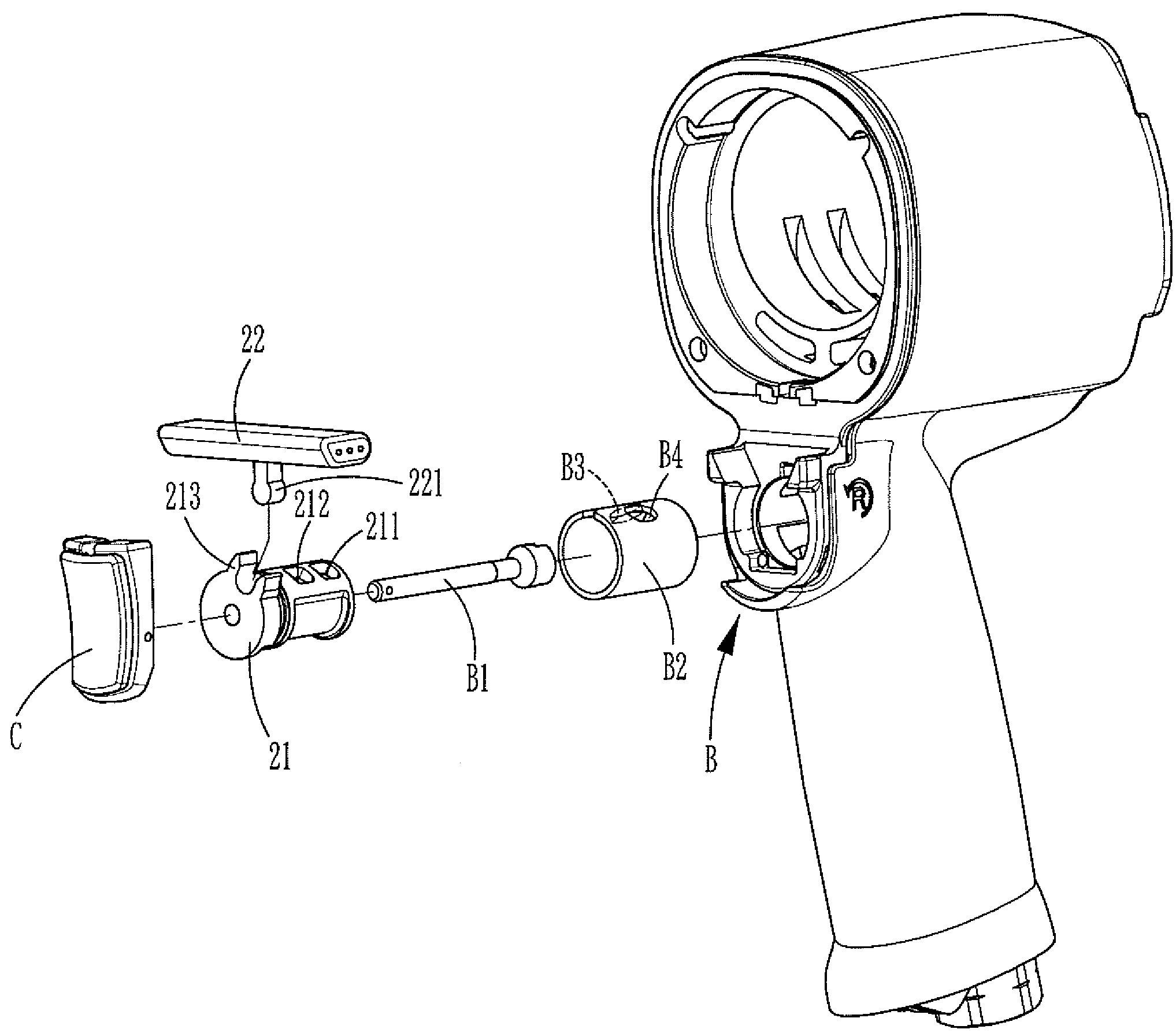
[0028]Referring to FIGS. 3-8, a rotating direction switching device for a pneumatic tool in accordance with the present invention is disposed between a valve seat B and a trigger C of the pneumatic tool A. The valve seat B is provided with a controlling shaft B1 and a valve sleeve B2, and the valve sleeve B2 is provided with a clockwise rotation air hole B3 and a counterclockwise rotation air hole B4 for cooperating with a clockwise rotation air inlet passage D and a counterclockwise rotation air inlet passage E of the pneumatic tool A, respectively.

[0029]An embodiment of the rotating direction switching device comprises an air inlet valve 21 and a switch 22.

[0030]The air inlet valve 21 is a hollow tubular structure pivotally and rotatably ins...


PUM


Abstract

A rotating direction switching device for a pneumatic tool comprises an air inlet valve and a switch. The air inlet valve is driven to switch the rotating direction of the pneumatic tool by controlling the switch, thus simplifying the operation of switching between the clockwise mode and counterclockwise mode, and facilitating the operation by a single hand. Especially, no matter users who are right hand or left hand dominated could easily operate the pneumatic tool.

Description

BACKGROUND OF THE INVENTION[0001]1. Field of the Invention[0002]The present invention relates to a pneumatic tool, and more particularly to a pneumatic tool having a rotating direction switching device.[0003]2. Description of the Prior Art[0004]Among all kinds of locking members, screws and nuts are most widely used because of their advantages. Therefore, tools for rotating the screws and nuts also have a large space to develop. These tools should be rotatable so as to rotate screws and nuts. However, a conventional tool usually is only able to rotate in a single direction, so two tools with different rotating direction should be prepared during work, and users have to alternately use the two tools, thus wasting time.[0005]In order to solve the abovementioned problem of the conventional tool and make screwing and unscrewing operation more convenient, a pneumatic wrench 10 having the function of switching rotating direction is developed, as shown in FIG. 1 and FIG. 2. A clockwise rot...

Claims


Application Information

Patent Timeline
Patent Type & Authority Applications(United States)
IPC IPC(8): B25D11/00
CPCB25B21/00
Inventor HUA, CHRIS
Owner BASSO IND CORP
Why Eureka
Try Eureka