Clutch System
a technology of clutch and spring diaphragm, which is applied in the direction of clutches, interengaging clutches, friction clutches, etc., can solve the problems of reducing the force of the pedal to compress the spring diaphragm in order to engage the clutch, hysteria in the clamp load, and the wear of the rim of the pressure plate, so as to facilitate the shaping of the spring diaphragm
- Summary
- Abstract
- Description
- Claims
- Application Information
AI Technical Summary
Benefits of technology
Problems solved by technology
Method used
Image
Examples
first embodiment
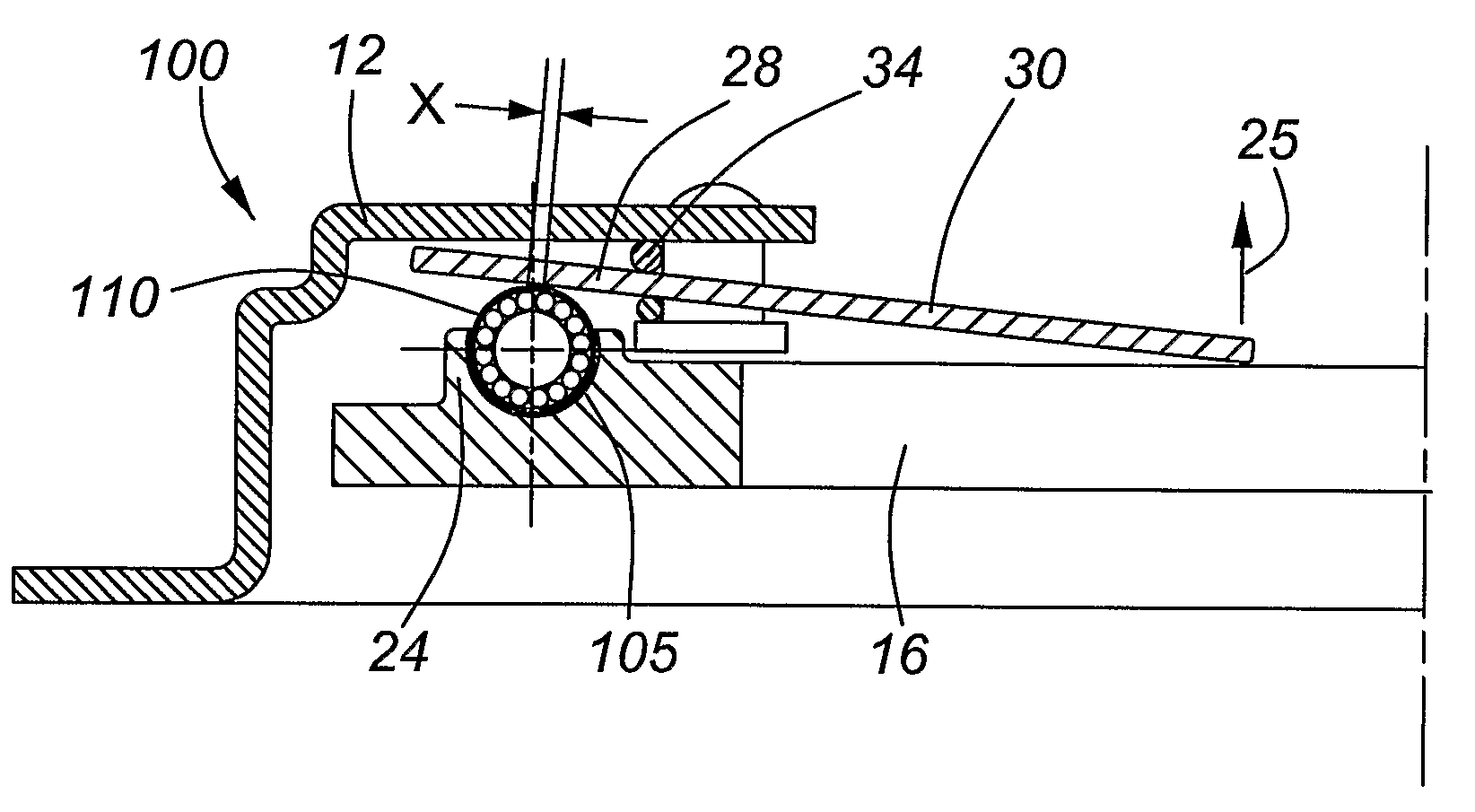
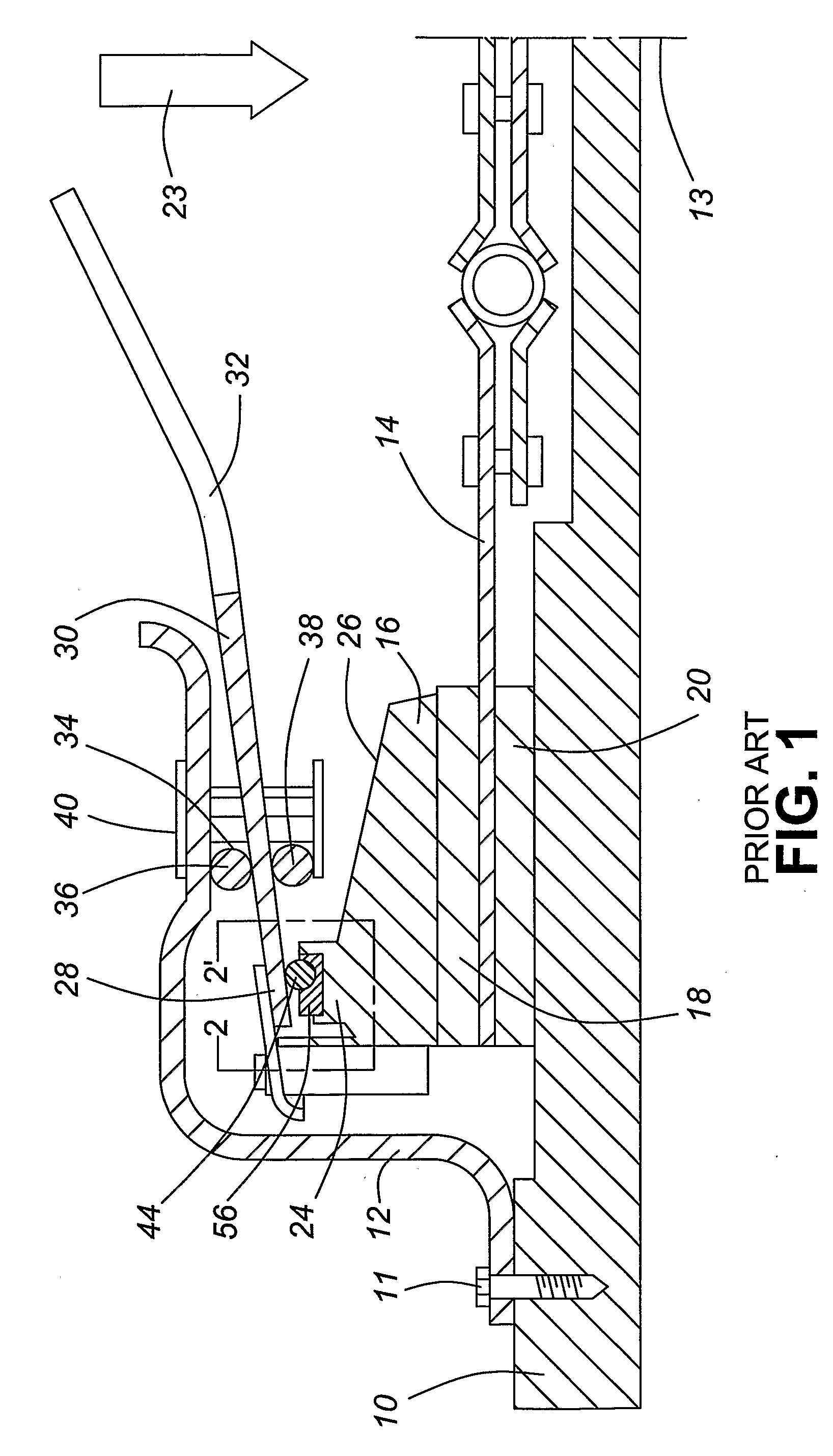
[0041]Referring now to the present invention, FIG. 6 is a side sectional view of the clutch system 100 in disengagement according to the present invention. While not all elements required to operate the clutch system 100 are shown, it is assumed that the skilled artisan is knowledgeable in that regard. In FIG. 6, the clutch system 100 shown includes a clutch cover 12, a pressure plate 16 with an annular ring 24, a spring diaphragm 30, and the shaft and rotational bearing arrangement 110 of the present invention. The shaft and rotational bearing form a bearing contact between the base of the spring diaphragm and the surface 105 of the annular ring 24 of the pressure plate 16. As discussed earlier with reference to the prior art, to engage the clutch system 100 such that the spring diaphragm 30 acts as “a first class lever”. The fulcrum support 34, forming part of the clutch cover 12, acts a pivot point and lies between an inner end of the diaphragm where force is applied to generally...
second embodiment
[0047]FIG. 12 is a plan view of a pressure plate 24 with a modified annular rim 24A according to the present invention. FIG. 13 is a side sectional view of the modified pressure plate 24 taken along line 13-13 of FIG. 12. The modified annular rim has a plurality of recesses 130A, 130B, . . . , 130E, for each corresponding shaft and rotational bearing, as shown in FIG. 9. Each of the plurality of recesses 130A, 130B, . . . , 130E define a longitudinal axis 131A, 131B, . . . , 131E that is tangential to the outer circumference of the annular ring 24A. Each recess 130A, 130B, . . . , 130E may be further dimensioned to permit axial movement of the rotational bearing (not shown) along its respective longitudinal axis 131A, 131B, . . . , 131E. For example, the corresponding rotational bearing (not shown) for recess 130A has a longitudinal length Y and the bearing portion of the recess 130A has a longitudinal length of Z, thus permitting axial movement of the rotational bearing along the c...
third embodiment
[0051]FIG. 14 is a plan view of a pressure plate 16 with a modified annular rim 24B according to the present invention. The annular rim 24B defines a plurality of recesses 140A, 140B, . . . , 140I.
[0052]FIG. 15 is a side sectional view of the pressure plate 16 taken along line 15-15 of FIG. 14, showing two recesses 140I and 140D.
PUM
 Abstract
Description
Claims
Application Information
 - R&D
- Intellectual Property
- Life Sciences
- Materials
- Tech Scout
- Unparalleled Data Quality
- Higher Quality Content
- 60% Fewer Hallucinations
Browse by: Latest US Patents, China's latest patents, Technical Efficacy Thesaurus, Application Domain, Technology Topic, Popular Technical Reports.
© 2025 PatSnap. All rights reserved.Legal|Privacy policy|Modern Slavery Act Transparency Statement|Sitemap|About US| Contact US: help@patsnap.com


