
Integrated lip seal for weld contamination control

a technology of integrated lip seals and welds, which is applied in the direction of interengaging clutches, manufacturing tools, gearing, etc., can solve the problems of excessive wear on internal components and transmissions, affecting the quality of welds, so as to maximize the isolation of weld debris and the effect of interior contamination control

Inactive Publication Date: 2008-10-16
LUK LAMELLEN & KUPPLUNGSBAU BETEILIGUNGS KG
View PDF2 Cites 10 Cited by
  • Summary
  • Abstract
  • Description
  • Claims
  • Application Information

AI Technical Summary

Benefits of technology

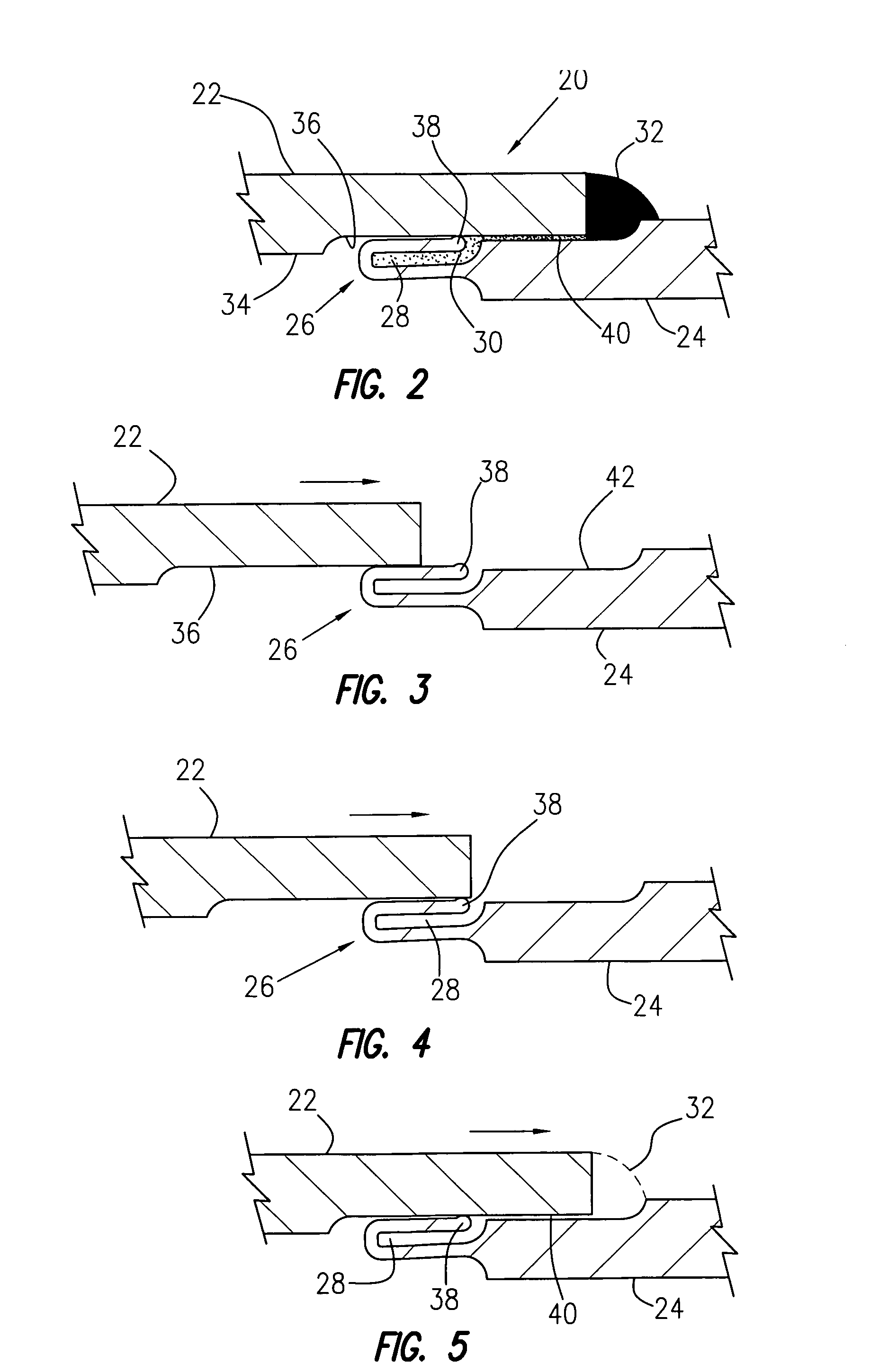
[0011]The method is preferably practiced, wherein the outer hardware component comprises an exterior surface and an interior surface and the curved and / or bent flange extension of the inner hardware component is sufficiently curved to engage with and form an interference fit with the interior surface of the outer component when the inner and outer components are in overlapping engagement. As a further preferred feature, the curved and / or bent flange extension, which may be in the form of a hook-shaped extension, comprises an enlarged terminal lip seal for maximizing weld contamination control. Similarly, the mating surfaces of the inner and outer hardware components are notched to form an indentation on the overlapping surfaces.
[0013]Other optional, but preferred features of the torque converter of the invention may include a bow or hook-shaped extension with an enlarged lip seal at the terminus of the hook for optimal sealing of the weld cavity for maximizing welding debris isolation and interior contamination control.

Problems solved by technology

However, in the process of sealing the front and back covers debris from the welding step has a tendency to enter the interior of the converter as contaminants.
Welding aggregate, if allowed to remain in the interior of torque converters for motor vehicles can cause excessive wear on internal components and to transmissions.
Consequently, current practices in the final assembly require additional steps for removal of debris, which is time consuming and costly, not only requiring more labor, but also requiring substantial capital investment for adding further floor space for the final assembly steps.
Weld contamination inside torque converters has been difficult to eliminate with current machining tolerances and processes.
Hence, while Select-Fit may reduce contamination from enclosure welding, the method is not entirely satisfactory.

Method used


Image

  • Integrated lip seal for weld contamination control
  • Integrated lip seal for weld contamination control
  • Integrated lip seal for weld contamination control

Examples


Embodiment Construction

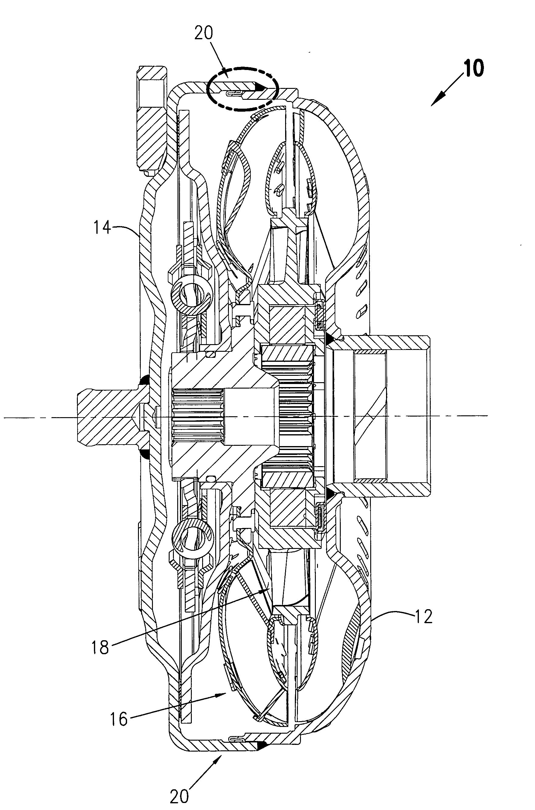
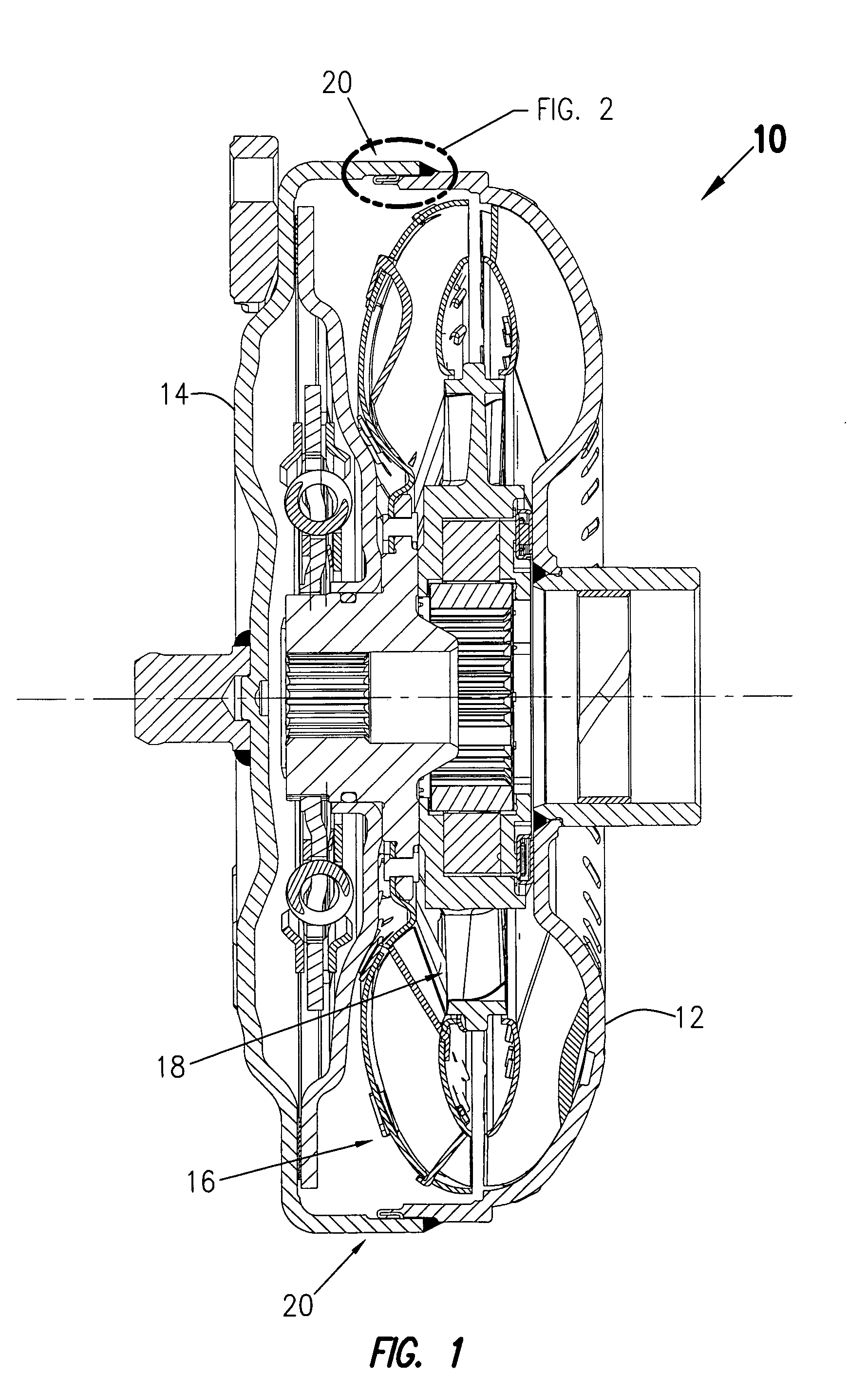
[0024]Turning first to FIG. 1, a torque converter 10 is illustrated with four principal components, namely back cover 12 as the pump shell, front cover 14, turbine 16 and stator 18. In torque converter 10, a fluid circuit is created by the pump, sometimes called an impeller, the turbine and the stator, sometimes called a reactor. The fluid circuit allows the engine to continue rotating when a vehicle is stopped, and accelerate the vehicle when desired by the driver.

[0025]As illustrated, torque converter 10 becomes a sealed chamber when front cover 14 is welded to back cover 12 by means of welded lap joint 20. FIG. 2 is an enlarged partial view of welded lap joint 20 according to the present invention consisting of front cover rim 22 arranged parallel with back cover rim 24. The terminus of rim 24 includes a narrowed extension or flange 26 having a generally U-shape or hook-like configuration when viewed sectionally, as to provide a central sealed weld cavity 28 as a reservoir for co...


PUM


Abstract

An integrated lip seal provides a containment system for isolating debris generated in welding an enclosure and preventing contamination of interiors of devices. The closure system is especially useful in preventing aggregate from welding contaminating the interiors of torque converters during the final stages of assembly.

Description

CROSS REFERENCE TO RELATED APPLICATION[0001]This application claims the benefit of U.S. provisional application No. 60 / 876,217, filed Dec. 21, 2006.FIELD OF THE INVENTION[0002]The present invention relates generally to welding debris isolation systems, and more particularly, to improved methods for welding enclosures that avoid introducing welding aggregate into interior spaces. The invention is especially advantageous for use in connection with sealing torque converters, wherein potentially damaging debris from welding is isolated from entry into the interior of such devices. The systems and methods provide a more economic alternative to time consuming manual flushing of converter interiors, and so called “Select-Fit” methods, for example.BACKGROUND OF THE INVENTION[0003]Torque converters are positioned between the engine and transmission case of motorized vehicles. They play an important role by controlling on / off power from the engine to the rest of the drive train. In addition, ...

Claims


Application Information

Patent Timeline
IPC IPC(8): F16D23/00C21D1/34
CPCB23K9/02B23K33/008F16H41/28F16H2041/243
Inventor ZAHNER, DERRICKAVINS, DAVID
Owner LUK LAMELLEN & KUPPLUNGSBAU BETEILIGUNGS KG
Learn More