Automatic controller for a beverage dispensing faucet

a beverage dispenser and automatic controller technology, applied in liquid handling, packaged goods, instruments, etc., can solve the problems of laborious process, electrically operated valves could become stuck in the open state, and not proportionally controlled

a beverage dispenser and automatic controller technology, applied in liquid handling, packaged goods, instruments, etc., can solve the problems of laborious process, electrically operated valves could become stuck in the open state, and not proportionally controlled

US20080251533A1Active Publication Date: 2008-10-16BERG

Image

  • Automatic controller for a beverage dispensing faucet
  • Automatic controller for a beverage dispensing faucet
  • Automatic controller for a beverage dispensing faucet

Examples


Embodiment Construction

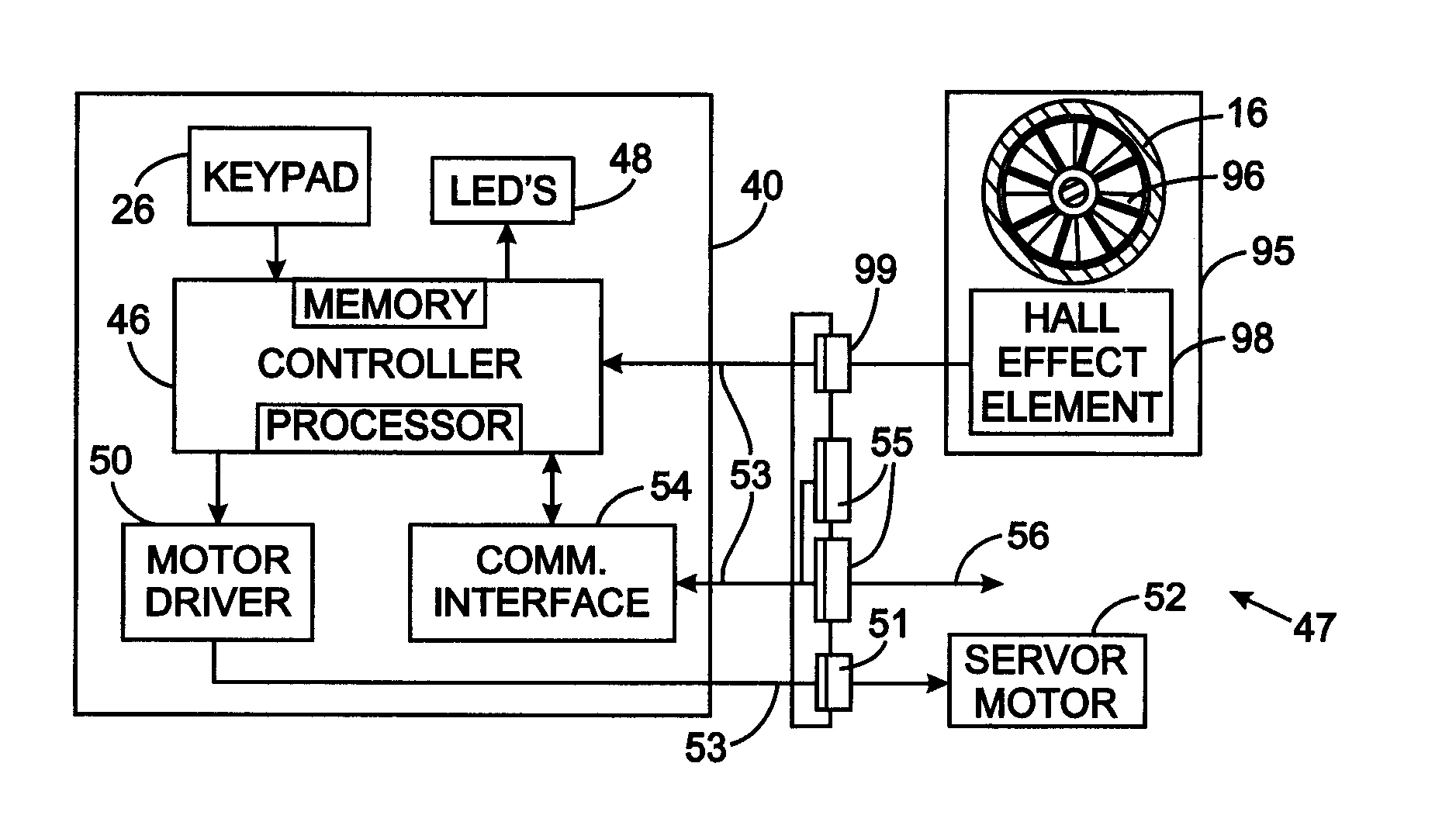
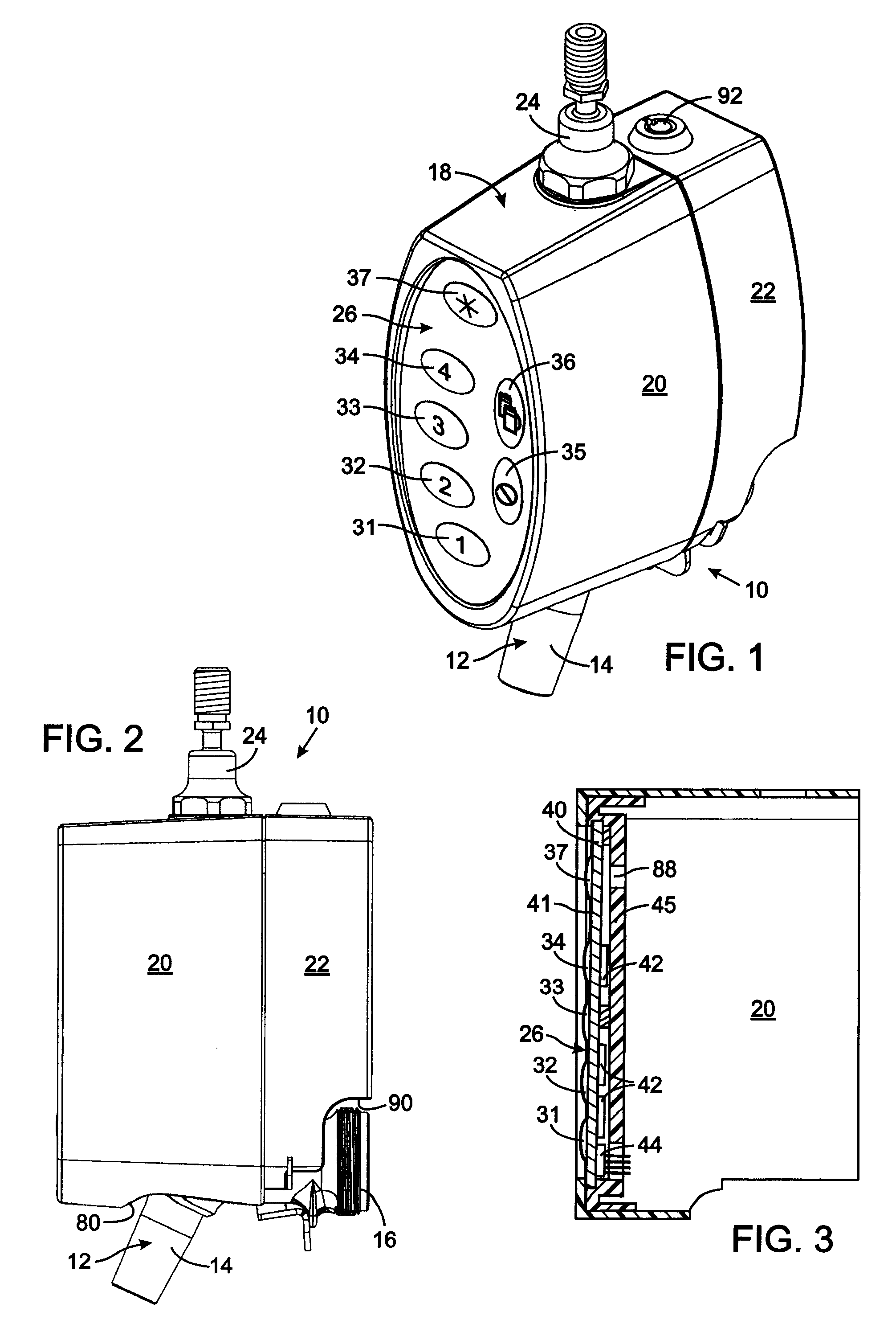
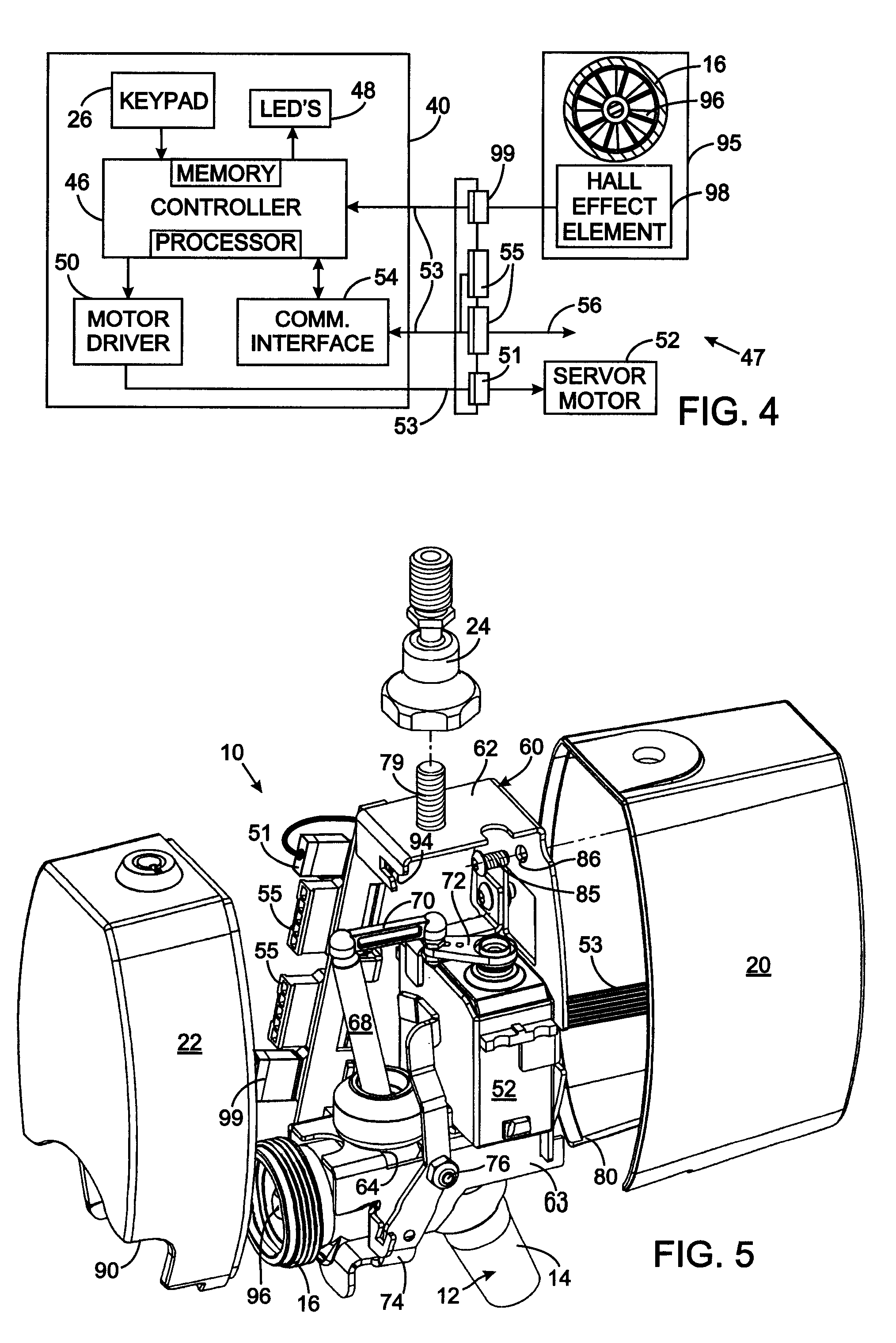
[0018]With initial reference to FIG. 1, a beverage dispenser 10 automatically dispenses different quantities of a beverage, such as beer, to fill a glass, a mug or a pitcher as selected by the user. The beverage dispenser 10 operates a faucet 12, such as a model 425SSB available from Perlick Corporation of Milwaukee, Wis. USA, that has a spout 14 and a fitting 16 for connection to a conduit through which beer is supplied under pressure from a keg (not shown). By using a commercially available faucet, the beverage dispenser does not have to be separately certified by NSF International as satisfying certain health and safety standards. The faucet 12, also referred to as a “tap”, is enclosed in a housing 18 that has a front cover 20 and a removable rear cover 22 that fit together. The front cover 20 includes a mount 24 for receiving a conventional faucet handle (not shown) which identifies the brand of beer being dispensed from the beverage dispenser 10. A bar typically has several of ...


PUM

PropertyMeasurementUnit
Forceaaaaaaaaaa
Magnetic fieldaaaaaaaaaa
Sizeaaaaaaaaaa

Abstract

A beverage dispenser has a faucet with a spout, a fitting for connection to a beverage supply, and a lever operated valve. A servo motor, coupled to the lever, operates the faucet and proportionally controls the flow of the beverage. That proportional flow control manages the amount of beverage foaming. A flow sensor has a magnetic turbine within the faucet and a Hall effect element that magnetically senses turbine motion and produces a signal indicating an amount of beverage flow. A keypad enables service personnel to designate various portions of the beverage to automatically fill serving containers of different sizes. A control circuit responds to activation of the keypad and to the flow sensor by operating the servo motor to dispense the related quantity of the beverage.

Description

CROSS-REFERENCE TO RELATED APPLICATIONS[0001]Not ApplicableSTATEMENT REGARDING FEDERALLY SPONSORED RESEARCH OR DEVELOPMENT[0002]Not ApplicableBACKGROUND OF THE INVENTION[0003]1. Field of the Invention[0004]The present invention relates to automatic beverage dispensing systems, and particularly to such systems for controlling the operation of a conventional dispensing faucet, commonly referred to as a “tap”.[0005]2. Description of the Related Art[0006]Beverages, such as beer and soft drinks, are frequently dispensed in taverns and restaurants from systems that have a faucet. A basic beverage dispensing system has manually activated faucets in which a person operates a valve lever either by hand or by a serving container inserted under the faucet. For a standard manual beer faucet, a lever is moved in one direction to open a valve, thereby sending beer through a spout into a container placed under the faucet. Movement of the lever in the opposite direction closes the valve and termina...

Claims


Application Information

Patent Timeline
16 Oct 2008
Publication
US20080251533A1
IPC
B67D5/30; B67D5/08; B67D5/16; B67D7/30; B67D7/08; B67D7/16
CPC
B67D1/0888; B67D1/1243; B67D1/1405; G01F1/115; G01F15/003; B67D1/1477; B67D2001/1483
Inventors
GILES, THOMAS E.; PURSELL, WILLIAM L.