Portable Type Fastener Driving Tool

a technology of driving tool and fastener, which is applied in the direction of manufacturing tools, stapling tools, nailing tools, etc., can solve the problems of limited length of single nail connecting body, difficulty in fastening, and difficulty in fastening

Active Publication Date: 2008-10-16
JPF WORKS
View PDF8 Cites 26 Cited by
  • Summary
  • Abstract
  • Description
  • Claims
  • Application Information

AI Technical Summary

Problems solved by technology

As a result, in this mode, the fastener connecting body cannot be wound in a coil shape.
However, since there are limits on the length of the magazine to maintain easy handle and operation for the nail driving device users, there are limits on the length of a single nail connecting body (limits on the number of nails which can be used to make up a single nail connecting body).
Therefore, in operations which involve driving a large quantity of nails in a short period of time such as when buildings are built using the 2×4 method, it is disadvantageous in that the nail connecting body must be frequently replaced.
However, air tools present problems in that they require an air compressor so that maneuverability is lacking on the work site.
In addition, since an air hose bring resisting effect to the movement of the tool, there are problems in that a heavy burden in placed on the operator.
It is unpleasant for an operator to carry out fastening operations while manipulating a hose at a work site which is cluttered with many members.
However, the prior art gas tool was inconvenient in that it could only be used with a rectilinear nail connecting body so that the nail connecting bodies had to be replaced frequently within a short period of time at a work site where many nail driving operations were being carried out.

Method used


Image

  • Portable Type Fastener Driving Tool
  • Portable Type Fastener Driving Tool
  • Portable Type Fastener Driving Tool

Examples


Embodiment Construction

[0039]Next, we shall describe a mode in which the invention in this application is applied to the nail driving device based on figures. FIG. 1 through FIG. 26 are the first practical embodiment (main embodiment) of the present invention.

BRIEF EXPLANATION OF FIGURES

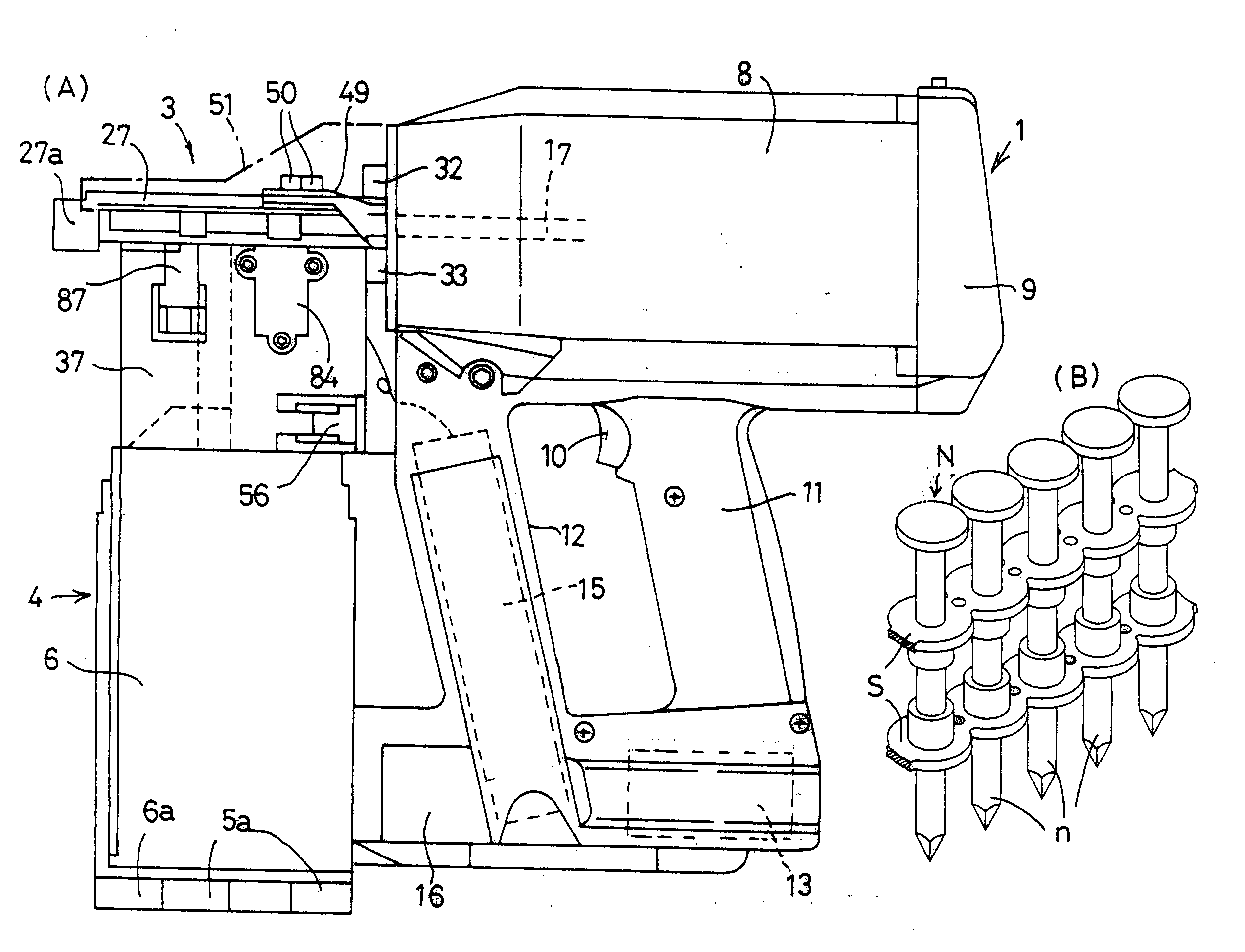
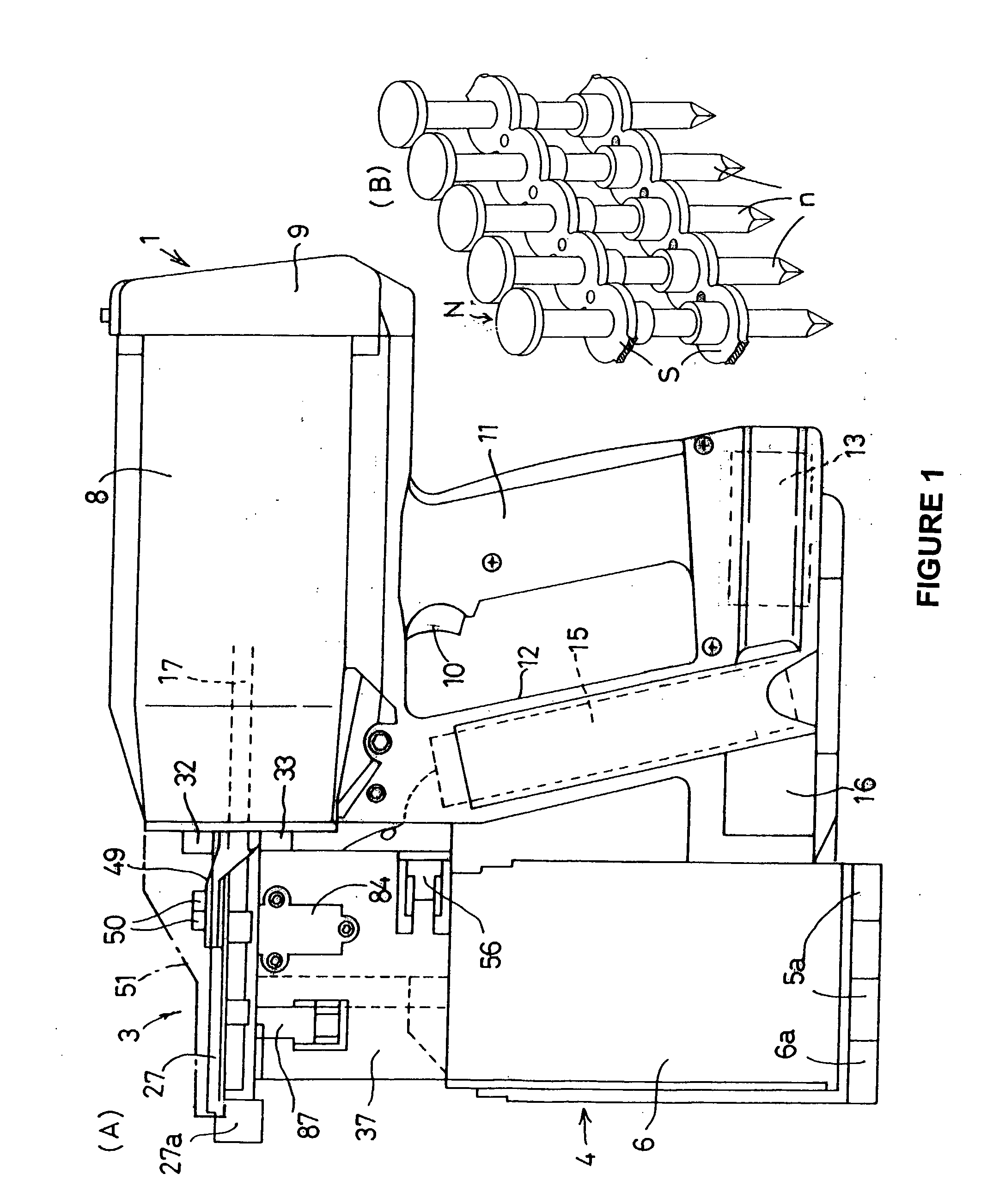
[0040]FIG. 1 (A) Right lateral view of gas combustion type nail driving device; FIG. 1 (B) a partial inclined view of the nail connecting body.

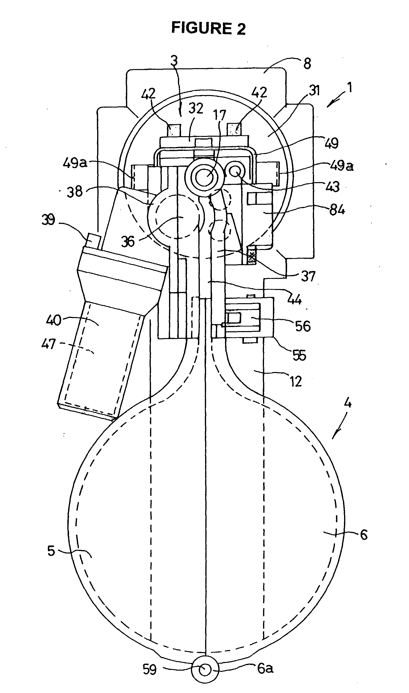
[0041]FIG. 2 Frontal view of the nail driving device.

[0042]FIG. 3 Frontal view showing the magazine when it is open.

[0043]FIG. 4 Vertical lateral view of the nail driving device.

[0044]FIG. 5 Right lateral view of the head part.

[0045]FIG. 6 Inclined view of head part when seen from the front and left, at an incline.

[0046]FIG. 7 (A). a partial exploded inclined view of the head part; FIG. 7 (B) a sectional view of (A) seen along B-B.

[0047]FIG. 8 An exploded inclined view of the head part and the main body.

[0048]FIG. 9 An exploded inclined view of the head part and the magazine.

[0049]F...


PUM

PropertyMeasurementUnit
pressureaaaaaaaaaa
electric poweraaaaaaaaaa
shapeaaaaaaaaaa

Abstract

A gas combustion type coil nailer is provided with (a) a main body (1) which is provided with combustion chamber; (b) a head part (3) which is disposed on the front surface of this; and (c) a magazine 4 which is disposed on the bottom surface of the head part (3) so that it can be attached and detached easily. A coil shaped nail connecting body is loaded onto the magazine (4). The head part (3) is provided with (d) a guide tube (35) through which the rod (17) and the nail n pass; and (e) with a feed motor (47). The nail connecting body N is fed to the guide tube (35) by a feed gear which is driven by the feed motor (47). Power is supplied to the feed motor (47) from a battery. The rod (17) is driven and the nail is fed by separate motive forces so that the nail can be fed reliably without adversely affecting the accuracy and reliability of the driving capacity of the rod (17).

Description

TECHNICAL FIELD[0001]The present invention relates to a portable type fastener driving tool which is used to drive fasteners such as nails and pins into a workpiece by hammering them in the axial direction.TECHNICAL BACKGROUND[0002]Portable type fastener driving tools can be classified as nail driving devices, pin driving devices (or tack driving devices) and staple driving devices and the like on the basis of the type of fastener which is being driven. On the other hand, they can be classified as devices using compressed air, the pressure of combustion, the brisance of gunpowder and electricity and the like on the basis of the driving source.[0003]In any case, fastener driving tools are provided with rods which are used for driving and continuous driving is permitted by supplying the fasteners one by one to the front of the rod.[0004]Fasteners which are used with fastener driving tools are made to connecting bodies which are connected by connecting material. The fastener connecting...

Claims


Application Information

Patent Timeline
Patent Type & Authority Applications(United States)
IPC IPC(8): B25C1/18B25C1/00B25C1/08
CPCB25C1/003B25C1/005B25C1/08B25C1/00
Inventor UEJIMA, YASUTSUGUYAMAKAWA, KEIJI
Owner JPF WORKS
Why Eureka
Try Eureka