White balance correcting method and image-pickup apparatus

a technology of image pick-up apparatus and white balance correction, which is applied in the direction of color television details, television systems, color signal processing circuits, etc., can solve the problems of low accuracy of final white balance gain calculated by digital cameras described in japanese patent application laid-open no. 2003-309854

Inactive Publication Date: 2008-10-16
FUJIFILM CORP
View PDF1 Cites 47 Cited by
  • Summary
  • Abstract
  • Description
  • Claims
  • Application Information

AI Technical Summary

Benefits of technology

[0031]As the present invention is adapted to be able to correctly predict the amount of flash reached, which is the amount of flash reached on a main subject in the main emission, and perform white balance correction according to the predicted amount of light reached, the present invention can appropriately perform white balance correction on the main subject even if a mixed light of flash light and ambient light is radiated on the main subject.

Problems solved by technology

The image processing apparatus described in Japanese Patent Application Laid-Open No. 2003-283918 has a problem in that it cannot perform preferable white balance correction, as a proportion of flash light radiated on the main subject changes according to a distance (a high proportion of flash light is radiated for a short distance, and a low proportion of flash light is radiated for a long distance) even if the same amount of flash is emitted.
The digital camera described in Japanese Patent Application Laid-Open No. 2003-309854 also has a problem in that it cannot perform preferable white balance correction for the reasons below: Although the digital camera decides a weighing factor for performing weighing-adding on the flash gain and the white balance gain for stationary light based on both of the brightness values on a subject for the pre-emitted image and the non-pre-emitted image, the relationship of ‘amount of pre-emission reached:outside light=present amount of pre-emission reached:outside light’ is not established here because the amount of emission in a main emission differs from the amount of emission in the pre-emission.
As a result, the final white balance gain calculated by the digital camera described in Japanese Patent Application Laid-Open No. 2003-309854 has low accuracy.

Method used


Image

  • White balance correcting method and image-pickup apparatus
  • White balance correcting method and image-pickup apparatus
  • White balance correcting method and image-pickup apparatus

Examples


first embodiment

[0074]FIG. 3 is a flowchart indicating the first embodiment of the digital camera 10 according to the present invention, specifically showing calculation of the WB gain in the flash photographing.

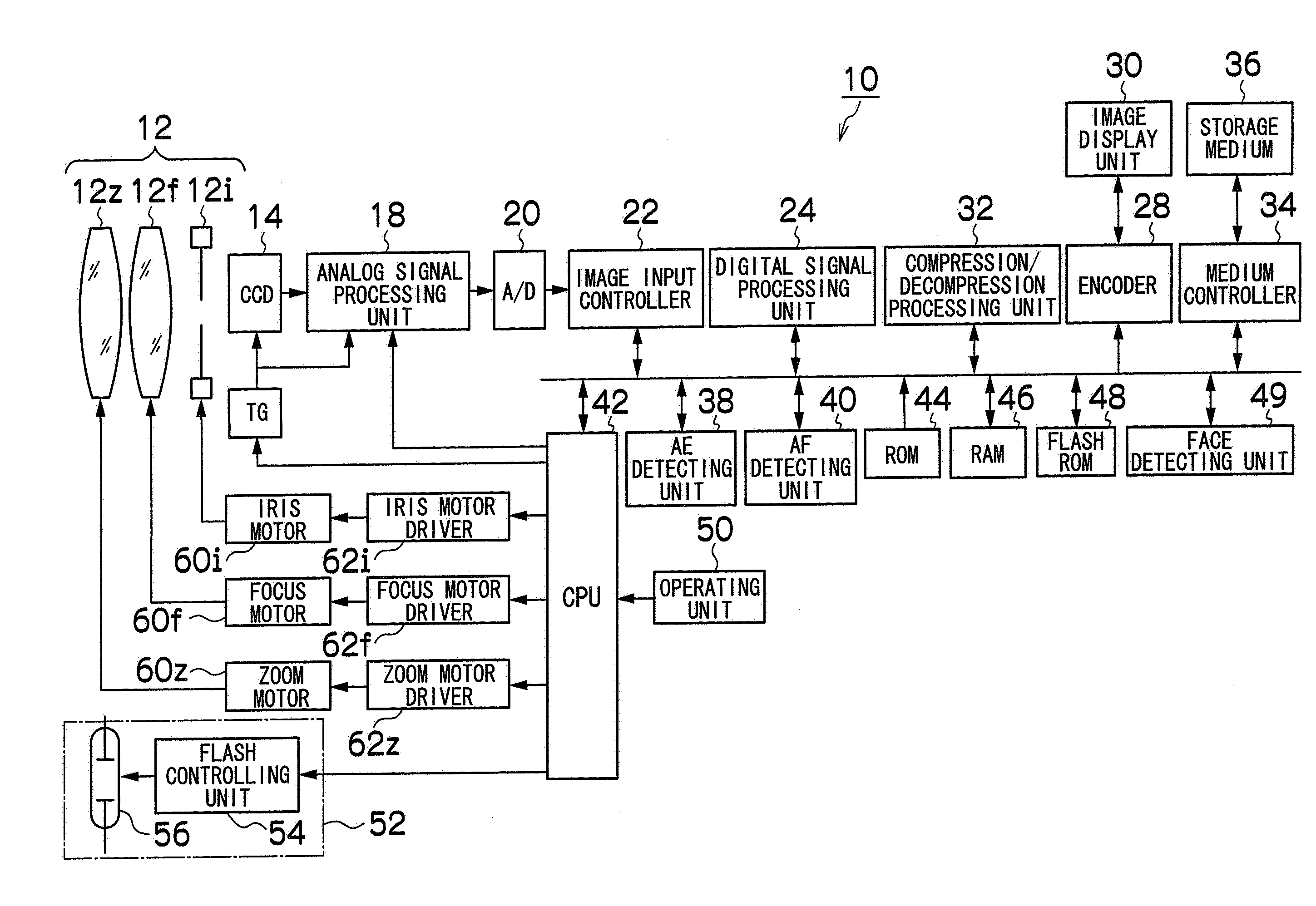
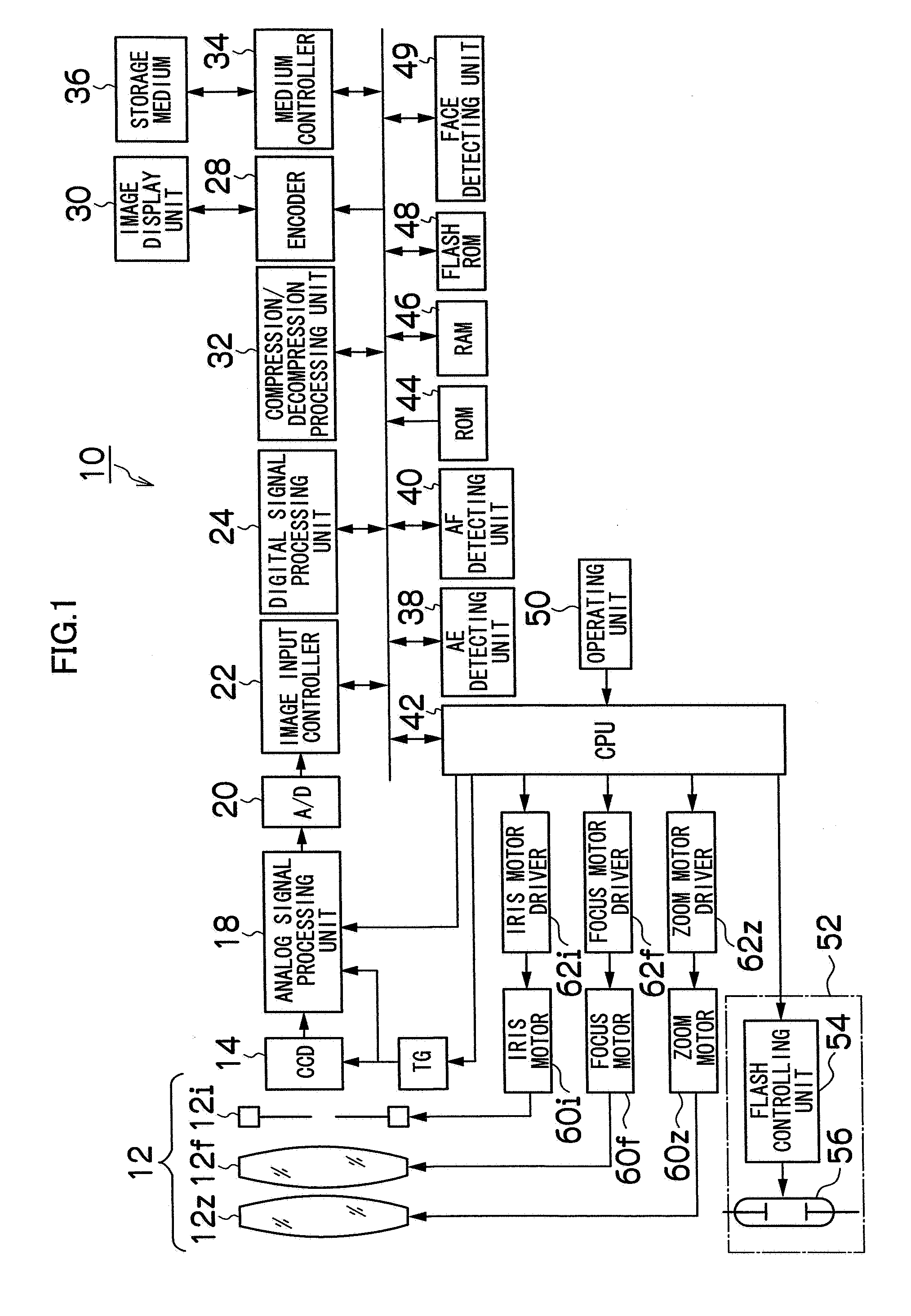
[0075]In the figure, when the shutter button is pressed all the way down, the non-emitted image and the pre-emitted image for metering flash are photographed before the main photographing (switch S10). That is, the non-emitted image is captured without emitting the flash device 52 before the main photographing, and then the flash device 52 is caused to perform the pre-emission with a predetermined amount of emission and the image is photographed, and the pre-emitted image photographed in the pre-emission is captured. The non-emitted image and the pre-emitted image may be photographed in the reverse order.

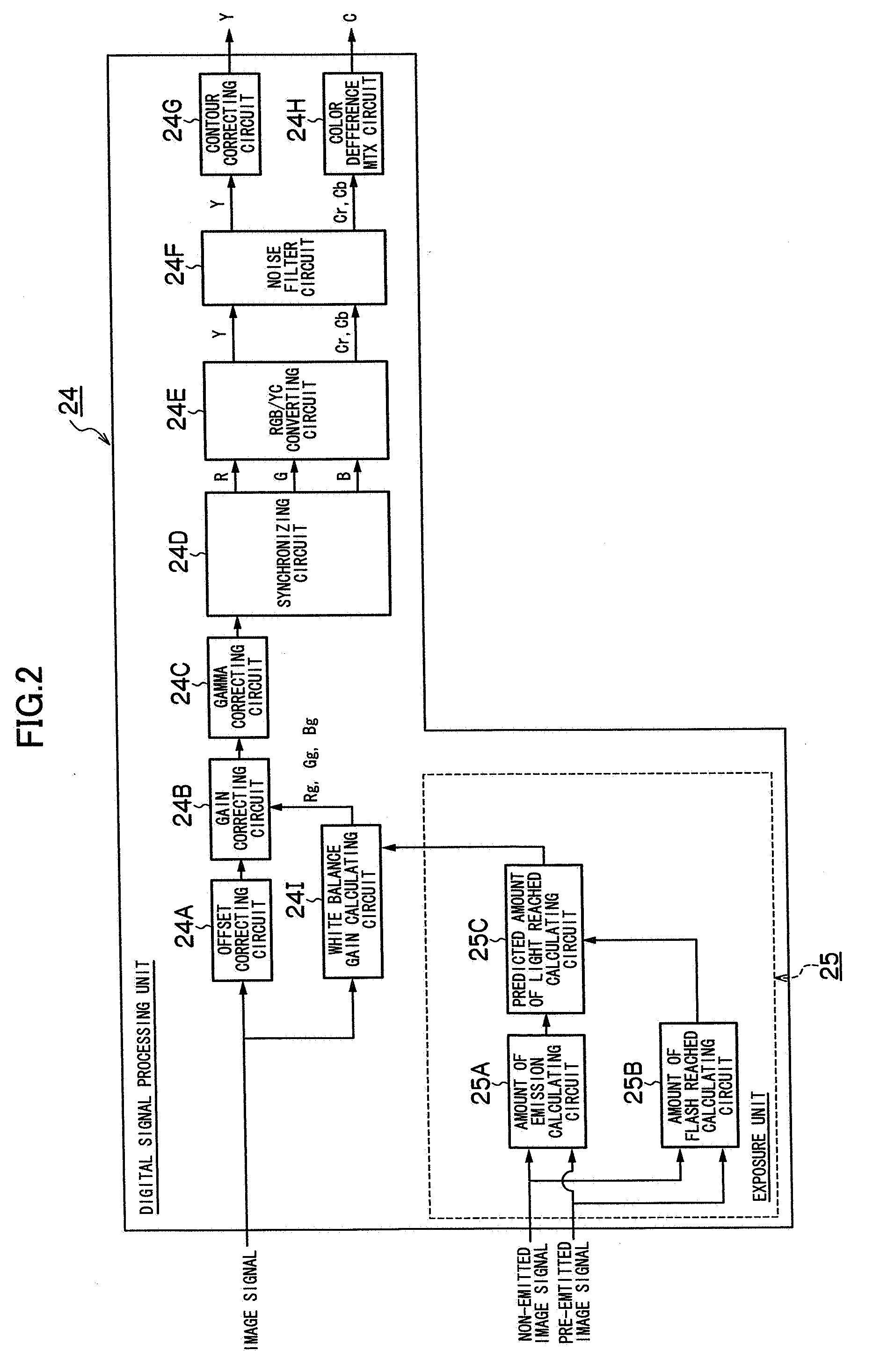
[0076]Then, an amount of emission calculating circuit 25A in the metering unit 25 shown in FIG. 2 calculates the amount of emission in the main emission required for photographing the main ...

second embodiment

[0106]FIG. 7 is a flowchart showing a second embodiment of the digital camera 10 according to the present invention. The same parts as those in the first embodiment shown in FIG. 3 are designated by the same step numbers and omitted from the detailed description.

[0107]The second embodiment is for processing a human face as a main subject when the face is detected. As shown in FIG. 7, the second embodiment is the first embodiment with processing of the steps S30, S32 and S34 added.

[0108]At step S30, whether the angle of view of each of the non-emitted image and the pre-emitted image photographed at step S10 includes a face or not is determined. If no face is included, the operation proceeds to step S12, where the same processing as that in the first embodiment is performed. If a face is included, the operation proceeds to step S32.

[0109]At step S32, the amount of emission in the main emission required for photographing the main subject at the target brightness value is calculated bas...

third embodiment

[0117]FIG. 10 is a flowchart showing the third embodiment of the digital camera 10 according to the present invention. The same parts as those in the first embodiment shown in FIG. 3 are designated by the same step numbers and omitted from the detailed description.

[0118]The third embodiment is for preventing the variation in the amount of emission in the main emission from affecting calculation of the WB gain (white balance correction). As shown in FIG. 10, the third embodiment is the first embodiment with processing at steps S40, S42, S44 and S46 added.

[0119]At step S40, the brightness value is calculated from the main emitted image obtained at the flash photographing (main photographing) and whether the brightness value is appropriate (target brightness value) or not is determined. If the target brightness value is matched, the operation proceeds to step S20 as in the first embodiment. If the target brightness value is not matched, the amount of emission in the main emission is co...


PUM


Abstract

The present invention provides a white balance correcting method and image-pickup apparatus which are able to perform white balance correction on a main subject even if mixed light of flash light and ambient light is radiated on the main subject, as the method and the apparatus are adapted to correctly predict the amount of flash reached, which is the amount of light reached a main subject in the main emission, for performing white balance correction according to the predicted amount of light reached.

Description

BACKGROUND OF THE INVENTION[0001]1. Field of the Invention[0002]The present invention relates to a white balance correcting method and image-pickup apparatus, and more specifically to a technique for performing optimal white balance correction in flash photography.[0003]2. Description of the Related Art[0004]The flash-photographed image (hereinafter referred to as “main emitted image”) has different illuminating light sources for a main subject and a background (a main subject=ambient light+flash light, a background=ambient light). That hinders appropriate white balance correction.[0005]The ambient light illuminating the main subject in flash photographing has stronger effect on the whole image in recent years as digital cameras have had higher sensitivity. If white balance correction is performed with a white balance gain (hereinafter referred to as “flash gain”) for each color of R, G, B, which are preset in correspondence with light source colors of the flash, with those digital ...

Claims


Application Information

Patent Timeline
Patent Type & Authority Applications(United States)
IPC IPC(8): H04N9/73
CPCH04N5/23219H04N5/2354H04N9/735H04N23/611H04N23/74H04N23/88
Inventor FUJIWARA, SHINYA
Owner FUJIFILM CORP
Why Eureka
Try Eureka