LED lighting system for retrofitting an aircraft cabin fluorescent lighting system

a technology for aircraft cabins and led lighting, applied in general lighting, mass transit vehicle lighting, lighting support devices, etc., can solve the problems of short service life, difficult and/or time-consuming replacement, and incandescent lamps that may only convert approximately 10% of their power consumption into visible ligh

Active Publication Date: 2008-10-16
BE AEROSPACE INCORPORATED
View PDF6 Cites 34 Cited by
  • Summary
  • Abstract
  • Description
  • Claims
  • Application Information

AI Technical Summary

Problems solved by technology

In particular, an incandescent lamp may convert only approximately 10% of its power consumption into visible light, while a fluorescent lamp that produces as much useful visible light energy may require only one-third to one-quarter as much power.
Although fluorescent lighting systems are more energy efficient than comparable incandescent lighting systems, fluorescent lighting systems that are installed in aircraft passenger cabins (e.g., the foregoing-described system 100 that is shown in FIG. 1) present aircraft operators with a number of challenges in operating and maintaining the systems.
One challenge is that fluorescent systems employ glass lamps/bulbs that are subject to breakage, and therefore, are often difficult and/or time-consuming to replace safely.
Furthermore, fluorescent bulbs use high voltage AC power (e.g., 1000Vp-p) and sometimes have a short service life (e.g., approximately 9000 hours) that

Method used


Image

  • LED lighting system for retrofitting an aircraft cabin fluorescent lighting system
  • LED lighting system for retrofitting an aircraft cabin fluorescent lighting system
  • LED lighting system for retrofitting an aircraft cabin fluorescent lighting system

Examples


Embodiment Construction

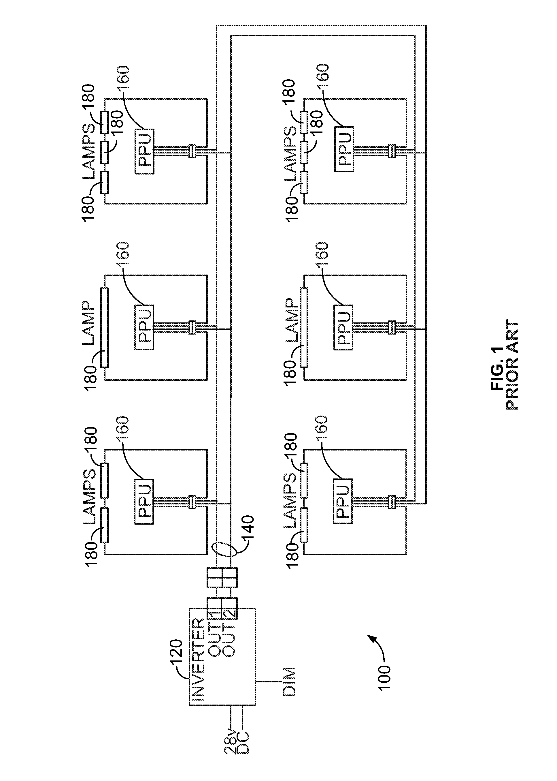
[0022]Turning now to the Figures, a light emitting diode (LED) lighting system is provided. Although the present LED lighting system is described with respect to retrofitting a conventional fluorescent lighting system that illuminates a passenger cabin of an aircraft, the present system is not limited as such and may be employed in other environments in which fluorescent lighting systems are configured. For example, the present LED lighting system may be configured and employed to retrofit fluorescent lighting in other passenger vehicles including busses, vans, cars, trains and boats. Indeed, the present LED lighting system may be configured and employed to retrofit other conventional fluorescent lighting systems known in the art that illuminate spaces such as the interiors of residences, offices, etc. as well as fluorescent-based architectural lighting systems that illuminate the exteriors of such spaces.

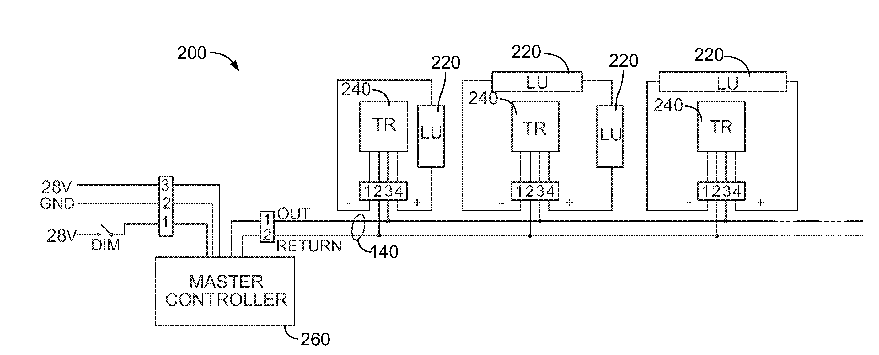
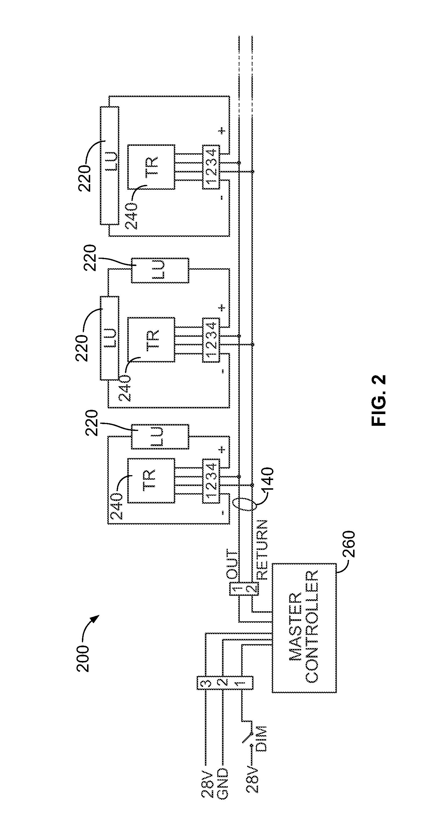
[0023]Turning now to FIG. 2, an example LED lighting system 200 in accordance ...


PUM


Abstract

A system and method are provided for retrofitting a fluorescent lighting system, for example a passenger cabin fluorescent lighting system on a vehicle such as an aircraft. The present system may include at least one LED lighting unit for replacing, in situ, at least one fluorescent light of the fluorescent lighting system, and a control module for replacing, in situ, at least one ballast-type unit of the fluorescent lighting system that illuminates the at least one fluorescent light. The present system may further include a master control module, which may replace, in situ, an inverter of the fluorescent lighting system. The present method may include steps of: replacing at least one fluorescent light, in situ, with at least one LED lighting unit; and replacing at least one ballast-type unit, in situ, with at least one control module configured to control illumination of the LED lighting unit.

Description

CROSS-REFERENCE TO RELATED PATENT APPLICATIONS[0001]This patent application claims the benefit of U.S. Provisional Patent Application No. 60 / 911,659, filed Apr. 13, 2007, the disclosure of which is incorporated herein in its entirety.FIELD OF THE INVENTION[0002]This invention pertains generally to lighting systems. More particularly, this invention relates to an LED lighting system that is configured to retrofit an aircraft cabin fluorescent lighting system in a plug-and-play manner.BACKGROUND OF THE INVENTION[0003]Fluorescent lighting fixtures have been employed ubiquitously for the past several decades, in residences, offices, institutional, commercial, industrial, and a host of other environments, as energy-efficient alternatives to incandescent and other types of lighting fixtures that use less efficient light sources. Fluorescent light sources are significantly more efficient than incandescent light sources of an equivalent brightness, because more of the energy consumed by a f...

Claims


Application Information

Patent Timeline
IPC IPC(8): F21V23/04
CPCB60Q3/025B60Q3/0259B60Q2900/10B64C2027/8236B64D2011/0038F21S4/008F21V23/06F21V31/005F21Y2101/02H05B33/0803H05B33/0815Y02B20/386F21S4/28F21Y2115/10B60Q3/43B60Q3/47B64D2203/00H05B45/37Y02B20/30H05B45/3578
Inventor HANCOCK, GARYJOHANNESSEN, ERIC
Owner BE AEROSPACE INCORPORATED
Why Eureka
Try Eureka