Magnetically sequenced pneumatic motor

a pneumatic motor and magnetic sequence technology, applied in the field of pneumatic devices, can solve the problems of inability to achieve smooth mechanical motion of pneumatic motors, inability to control the speed of pneumatic motors, and intermittent consumption of kinetic energy by switching devices

Active Publication Date: 2008-10-16
CARLISLE FLUID TECH INC
View PDF64 Cites 59 Cited by
  • Summary
  • Abstract
  • Description
  • Claims
  • Application Information

AI Technical Summary

Problems solved by technology

Conventional pneumatic motors are inadequate in some regards.
For example, the mechanical motion produced by the pneumatic motor may not be smooth.
When operating, the switching devices may intermittently consume a portion of the kinetic energy that the pneumatic motor would otherwise output.
Variations in flow rate may be particularly problematic when pumping a coating liquid to a spray gun.
The spray pattern may contract when the flow rate drops and expand when the flow rate rises, which may result in an uneven application of the coating liquid.
The switching devices in conventional pneumatic motors can produce other problems as well.
For example, some types of switching devices, such as reed valves, may quickly wear out or be damaged by vibrations from the pneumatic motor, thereby potentially increasing maintenance costs.
Further, some types of switching devices may be unresponsive at low pressures, e.g., less than 25 psi.
Unresponsive switching devices may impede use of the pneumatic motor in applications where low-speed motion is desired or higher pressure air supplies are not available.

Method used


Image

  • Magnetically sequenced pneumatic motor
  • Magnetically sequenced pneumatic motor
  • Magnetically sequenced pneumatic motor

Examples


Embodiment Construction

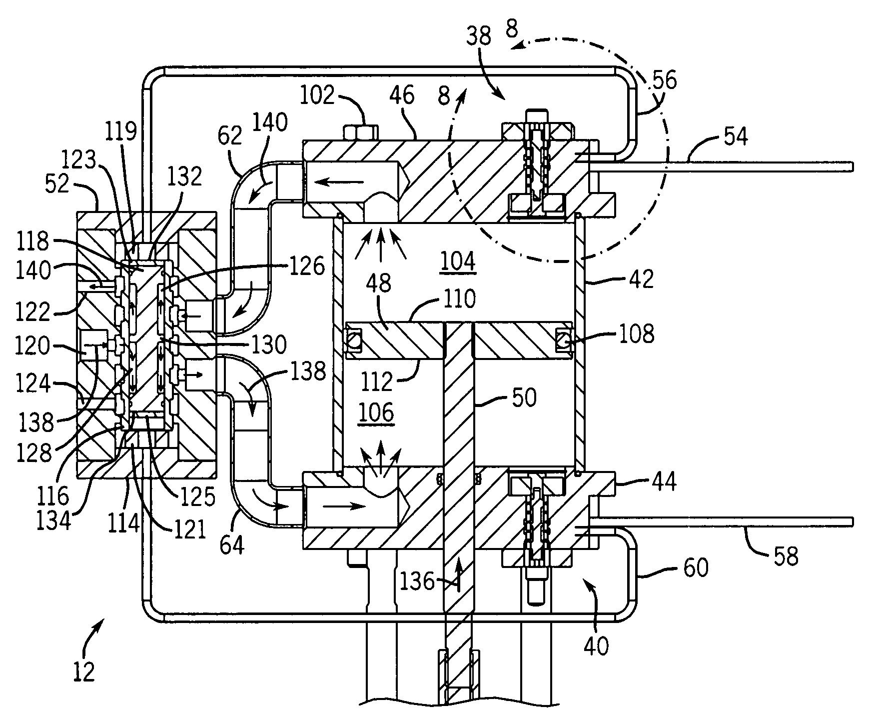
[0020]As discussed in detail below, some of the embodiments of the present technique provide a method and apparatus for coordinating air flow in a pneumatic motor. Of course, such embodiments are merely exemplary of the present technique, and the appended claims should not be viewed as limited to those embodiments. Indeed, the present technique is applicable to a wide variety of systems.

[0021]As used herein, the words “top,”“bottom,”“upper,” and “lower” indicate relative positions or orientations and not an absolute position or orientation. The term “or” is understood to be inclusive unless otherwise stated. The term “exemplary” is used to indicate that something is merely a representative example and not necessarily definitive or preferred. Herein, references to fluid pressures are gauge pressure (in contrast to absolute pressure) unless otherwise noted.

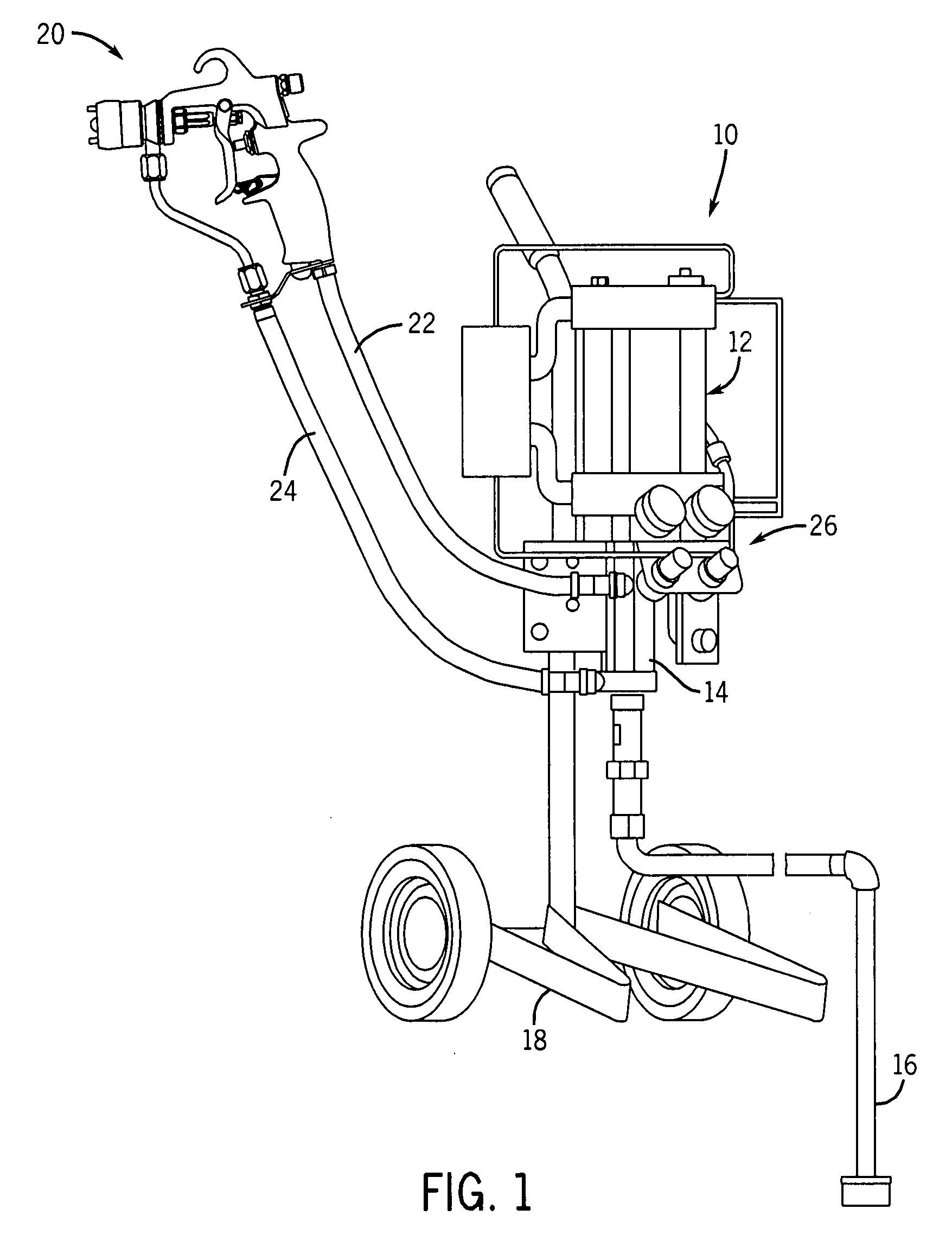
[0022]FIG. 1 depicts an exemplary spray system 10. The spray system 10 includes a pneumatic motor 12 that may address one or more ...


PUM


Abstract

A pneumatic motor having a piston and a magnetically actuated valve. The magnetically actuated valve may be adjacent the piston and, in some embodiments, include a spool valve.

Description

BACKGROUND[0001]The present invention relates generally to pneumatic devices and, in certain embodiments, to air motors with valves having magnetic detents.[0002]Pneumatic motors are often used to convert energy stored in the form of compressed air into kinetic energy. For instance, compressed air may be used to drive a reciprocating rod or rotating shaft. The resulting motion may be used for a variety of applications, including, for example, pumping a liquid to a spray gun. In some spray gun applications, the pneumatic motor may drive a pump, and the pump may convey a coating liquid, such as paint.[0003]Conventional pneumatic motors are inadequate in some regards. For example, the mechanical motion produced by the pneumatic motor may not be smooth. Switching devices in pneumatic motors may signal when to re-route pressurized air during a cycle of the motor. When operating, the switching devices may intermittently consume a portion of the kinetic energy that the pneumatic motor woul...

Claims


Application Information

Patent Timeline
Patent Type & Authority Applications(United States)
IPC IPC(8): F04B35/02
CPCF15B15/202F15B15/204F01B25/02F04B9/12F15B13/043F15B15/20
Inventor STRONG, CHRISTOPHER L.
Owner CARLISLE FLUID TECH INC
Why Eureka
Try Eureka