Method for producing welded resin material and welded resin material

a technology of welded resin and welded parts, which is applied in the direction of manufacturing tools, transportation and packaging, and other domestic objects, etc., can solve the problems of external disfigurement of products, damage to precision parts, and failure to join

Active Publication Date: 2008-10-16
MITSUBISHI ELECTRIC CORP
View PDF3 Cites 37 Cited by
  • Summary
  • Abstract
  • Description
  • Claims
  • Application Information

AI Technical Summary

Benefits of technology

[0010]The present invention has been developed for solving the aforementioned problems, and an object thereof is to provide such a method for producing a welded resin material, and a welded resin material, in that an excluded resin, even though it is formed, is prevented from being dropped off after laser welding.

Problems solved by technology

In the case where the contact is insufficient, heat transfer from the absorptive resin member to the transmissive resin member become insufficient to cause failure in joining.
The excluded resin solidified in the incisive shape is liable to be dropped off upon application of vibration or impact, and causes a problem in contamination of environments, in which the product having the molten part is used or transported.
In the case of a product having an internal space having a precision component, such as an electronic part, housed therein, there is a problem of damaging the precision part due to impact of the excluded resin dropped in the internal space.
Furthermore, even though the excluded resin is not dropped off, the incisive part exposed externally disfigures the product.
In order to fill the closed space with the molten material for welding, however, welding and sealing cannot be attained unless the closed space is filled with the molten material.
Accordingly, a large quantity of energy of laser light and a prolonged welding time are required, and there is a possibility of destabilizing the welding property.
Furthermore, the density of the surrounding resin is decreased to deteriorate the durability when the surrounding resin of the closed space is melted excessively.
In this method, the amount of the formed excluded resin can be reduced, but there is a risk of failure on joining when only a slight gap is formed at the contact part.
Thus, there is a problem of deterioration in productivity when the excluded resin is suppressed from being formed.

Method used


Image

  • Method for producing welded resin material and welded resin material
  • Method for producing welded resin material and welded resin material
  • Method for producing welded resin material and welded resin material

Examples


embodiment 1

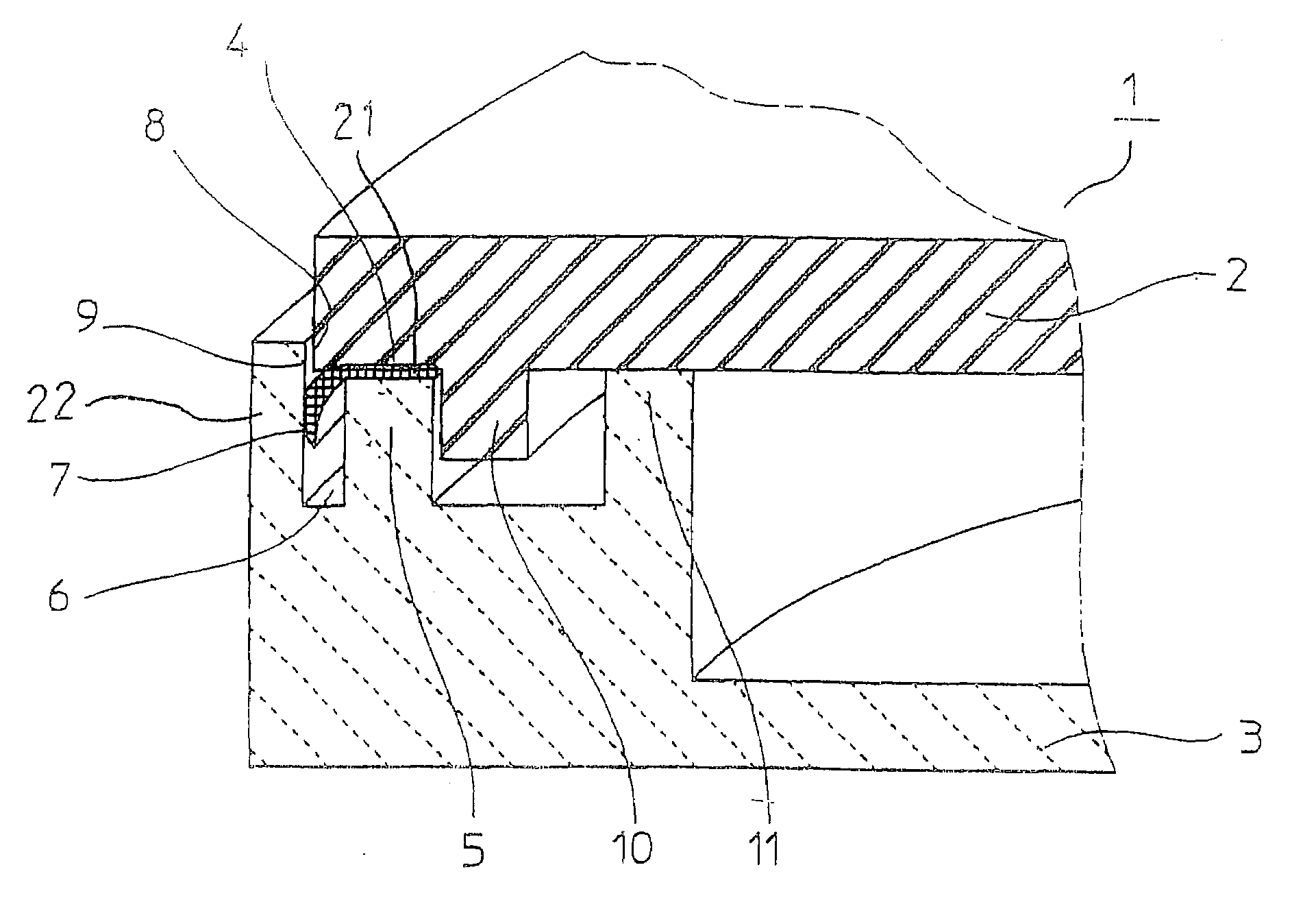
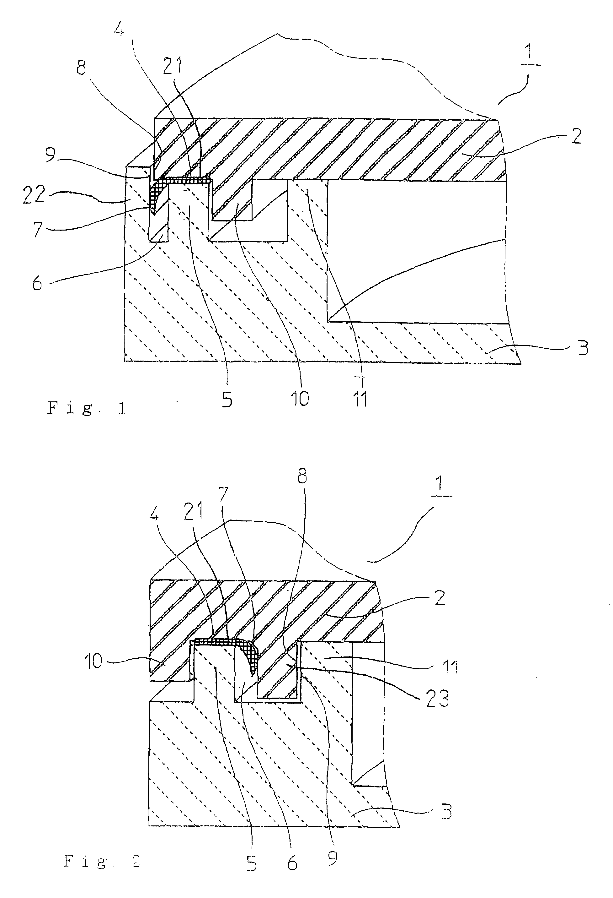
[0028]FIG. 1 is a partial cross sectional view showing an example of a welded resin material of an embodiment 1 of the present invention. The welded resin material will be described with reference to a sealed container 1 containing a cylindrical chassis with a bottom and a lid body as an example. The lid body 2 of the sealed container 1 is a resin member having transmissibility to laser light, and the cylindrical chassis with a bottom 3 is a resin member having absorptivity to laser light. A contact part 21 formed by making the resin members in contact with each other is welded to form a joined part 4. The joined part 4 is present between a top end of an annular rib (second annular projection) 5 provided on the chassis 3 and the lid body 2. The joined part 4 has been once melted by heating with laser light and then solidified upon welding. The rib 5 is provided in an annular form along the inner side of the outer periphery of the chassis 3, and a closed space 6 is provided on the ou...

embodiment 2

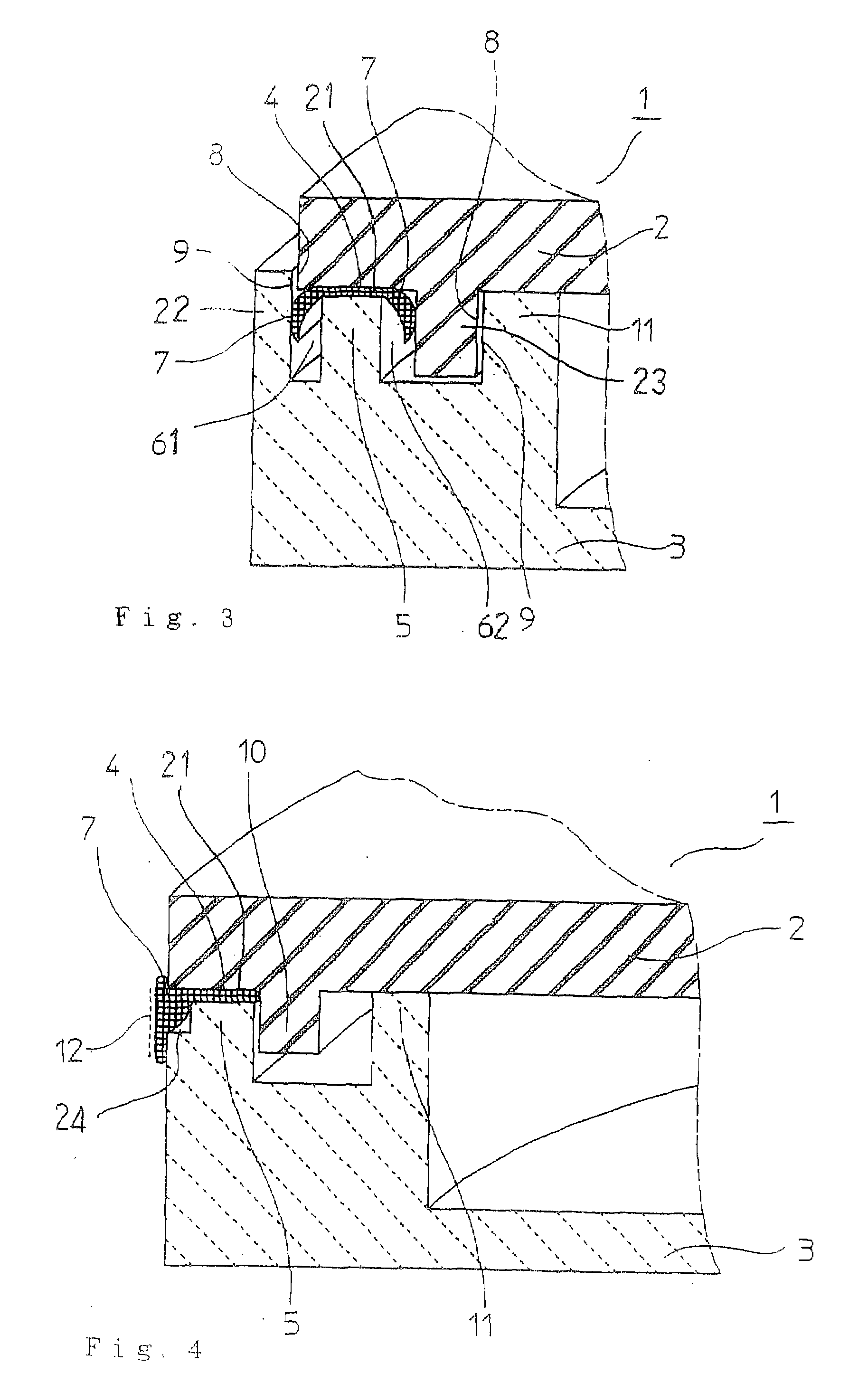
[0040]FIG. 4 is a partial cross sectional view showing an example of a welded resin material of the embodiment 2. The difference from the embodiment 1 is that it has no closed space for housing the resin excluded from the contact part 21. Since the fourth annular projection 10 provided on the lid body 2 is interdigitated on the inner circumference of the rib (second annular projection) 5, the resin 7 excluded from the contact part 21 is protruded outside the rib 5 and exposed to the outer circumference of the chassis 3 due to the absence of a closed space. The exposed surface of the excluded resin 7 is wholly or partially molded into a prescribed shape. In FIG. 4, numeral 24 denotes a reservoir for the excluded resin 7 provided in the chassis 3 as facing an end on the outer circumference of the contact part 21.

[0041]The shape of the molded exposed surface 12 is not particularly specified, and the contour of the cross section may be linear as shown in FIG. 4 or may be curved as shown...


PUM

PropertyMeasurementUnit
transmittanceaaaaaaaaaa
temperatureaaaaaaaaaa

Abstract

A method for producing a welded resin material contains steps of: superimposing a resin member having transmissibility to laser light and a resin member having absorptivity to laser light to form a contact part where the resin members are in contact with each other; forming a closed space that is adjacent to the contact part and faces one end of the contact part; and radiating the laser light from the resin member having transmissibility while pressing the resin members to each other through the contact part, so as to heat the contact part to melt a resin at the contact part, housing a resin excluded from the contact part through melting in the closed space, solidifying the resin melted at the contact part to weld the resin members.

Description

BACKGROUND OF THE INVENTION[0001]1. Field of the Invention[0002]The present invention relates to a method for producing a welded resin material by joining a resin member having transmissibility to laser light and a resin member having absorptivity to laser light, and to a welded resin material.[0003]2. Description of the Related Art[0004]Such a method has been well known in the art that a resin member having transmissibility to laser light having a specific wavelength and a resin part having absorptivity to laser light having the same wavelength are superimposed and irradiated with laser light from the side of the transmissive resin member to weld them. The principle of the method will be described briefly. Laser light passes through the transmissive resin with substantially no absorption and is absorbed in the vicinity of the surface of the absorptive resin member. The energy of the laser light thus absorbed is converted to heat, which heats the surface of the absorptive resin memb...

Claims


Application Information

Patent Timeline
Patent Type & Authority Applications(United States)
IPC IPC(8): B32B27/00
CPCB29C65/1616Y10T428/195B29C65/1635B29C65/1696B29C66/322B29C66/3242B29C66/326B29C66/3282B29C66/71B29C66/7332B29K2023/06B29K2067/00B29K2067/006B29K2069/00B29K2077/00B29K2081/04B29K2995/0027B29C65/1619B29C66/542B29C65/1674B29C65/1654B29C65/00B29C65/7829B29C66/112B29C66/114B29C66/7392B29C66/81267B29C66/8322B29L2031/712Y10T428/8305B29K2071/00B29K2067/003B29C65/16
Inventor ASADA, SHINSUKEHARA, TAKAFUMIFUJIMOTO, SEIZOTARUYA, MASAAKI
Owner MITSUBISHI ELECTRIC CORP
Why Eureka
Try Eureka