
Textile sleeve for protecting elongate members and method of construction

Inactive Publication Date: 2008-10-16
FEDERAL MOGUL WORLD WIDE
View PDF11 Cites 9 Cited by
  • Summary
  • Abstract
  • Description
  • Claims
  • Application Information

AI Technical Summary

Benefits of technology

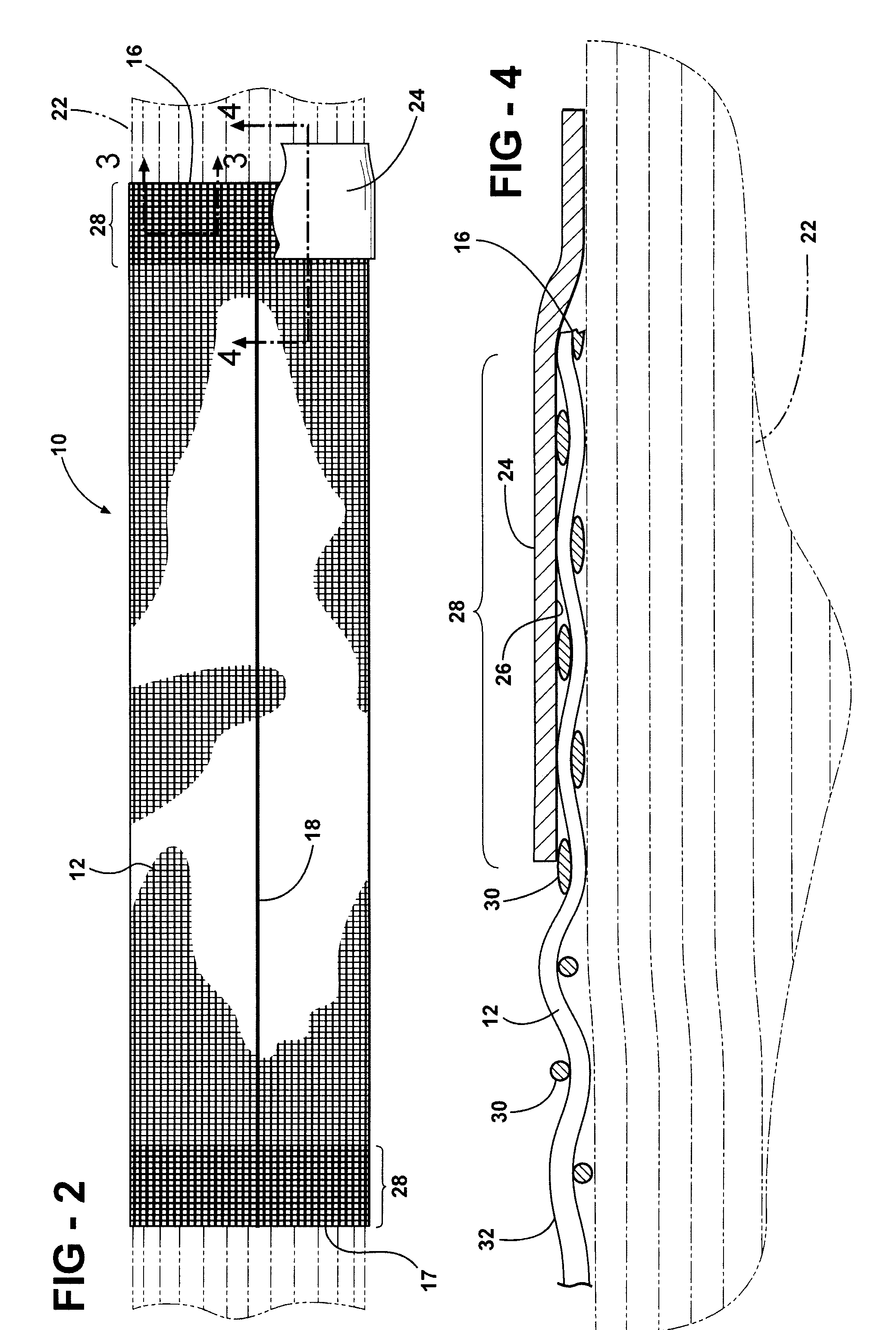
[0008]The invention concerns a textile sleeve for protecting elongate members. The sleeve has a wall constructed at least in part from generally round monofilaments. The sleeve wall provides a central space extending along a longitudinal axis between opposite ends. The monofilaments having a region with a permanently melted and flattened outer surface adjacent at least one of the ends. The melted and flattened region provides an increased surface area to which tape can be adhered, while also acting to reduce the potential for end fray of the filaments forming the textile sleeve.

Problems solved by technology

The poor adhesion results largely due to the reduced surface area provided by the convex surfaces of the round filaments 130 forming the sleeving 110.
This can result in unwanted exposure of the elongate member 122.

Method used


Image

  • Textile sleeve for protecting elongate members and method of construction
  • Textile sleeve for protecting elongate members and method of construction
  • Textile sleeve for protecting elongate members and method of construction

Examples


Embodiment Construction

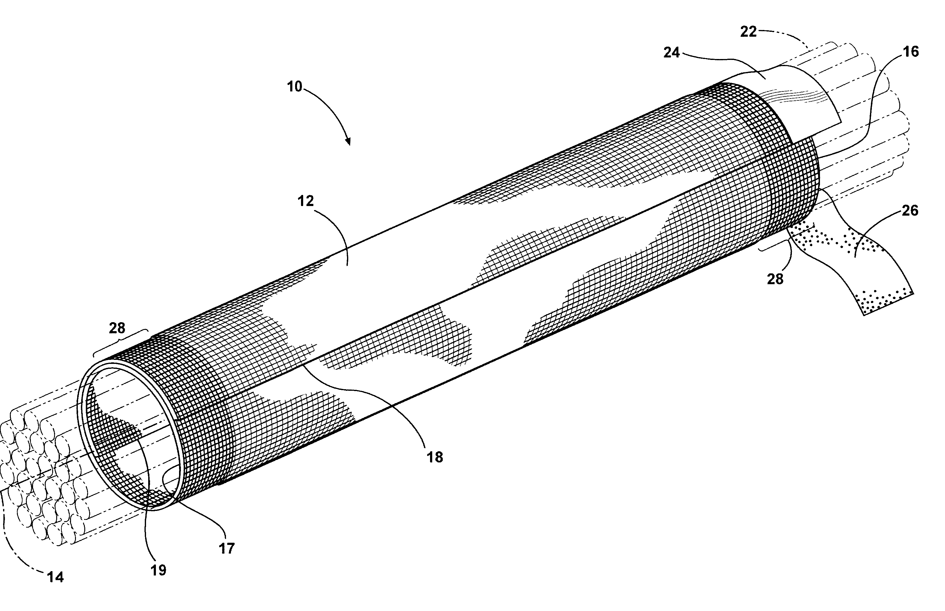
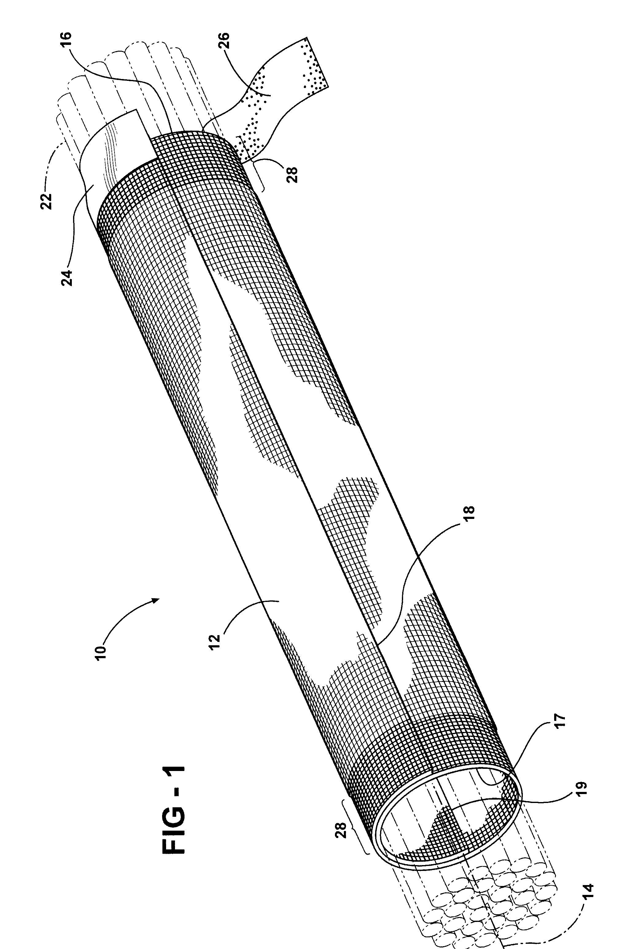
[0016]Referring in more detail to the drawings, FIGS. 1 and 2 illustrates a protective textile sleeve constructed in accordance with one presently preferred embodiment of the invention generally at 10. The sleeve 10 is constructed from an elongate textile substrate 12 that extends along a longitudinal axis 14 between opposite ends 16, 17. The substrate 12 can be knitted, braided, or woven, and has opposite selvages, referred to hereafter as free edges 18, 19 which either extend parallel to the axis 16 (the so-called “cigarette” wrap construction) or in a helical path (not shown) about the axis 16. In either case, the substrate 12 provides a central space 20 that receives elongate members 22 to be protected, such as a wiring harness or optical fibers, for example. The free edges 18 are generally unbound, and thus, can be opened or spread apart from one another to allow the elongate members 22 to be disposed or removed from the central space 20, as desired. Upon inserting the elongate...


PUM

PropertyMeasurementUnit
Lengthaaaaaaaaaa

Abstract

A textile sleeve for protecting elongate members and method of construction thereof provides a sleeve having a wall constructed at least in part from generally round monofilaments. The sleeve wall provides a central space extending along a longitudinal axis between opposite ends for receipt of the elongate members. The monofilaments have a region with a permanently melted and flattened outer surface adjacent at least one of the ends. The melted and flattened region provides an increased surface area to which tape can be adhered, while also acting to reduce the potential for end fray of the filaments forming the textile sleeve.

Description

BACKGROUND OF THE INVENTION[0001]1. Field of the Invention[0002]This invention relates generally to textile sleeves for protecting elongate members, and more particularly to textile sleeves having ends secured against relative axial movement to the elongate members.[0003]2. Related Art[0004]Protective sleeving is used throughout the automotive, industrial, marine, airline and aerospace industries to organize and protect elongate members, such as wiring harnesses and optical fiber cables, for example. The sleeving surrounds the elongate members and protects them against cuts, abrasion, radiant heat, vibration induced wear and other harsh environmental threats. When positioned within protective sleeving, the wiring or cables are also held together in a neat bundle, allowing a multiplicity of different items to be handled as a sub-assembly, thus saving time and effort during integration of the items into its end environment.[0005]Protective sleeving may be made by weaving, braiding or ...

Claims


Application Information

Patent Timeline
IPC IPC(8): B32B1/08B32B23/02
CPCF16L57/06H02G3/0481Y10T428/1362Y10T428/24785Y10T428/13D03D1/0043B32B3/00B32B5/02F16L57/00
Inventor YAMAGUCHI, HIROKI
Owner FEDERAL MOGUL WORLD WIDE
Learn More