
Battery pack

a battery pack and battery technology, applied in the field of batteries, can solve the problems of brittle deformation, electrical short, damage to notebook computers, etc., and achieve the effect of preventing crack formation

Inactive Publication Date: 2008-10-16
SAMSUNG SDI CO LTD
View PDF2 Cites 10 Cited by
  • Summary
  • Abstract
  • Description
  • Claims
  • Application Information

AI Technical Summary

Benefits of technology

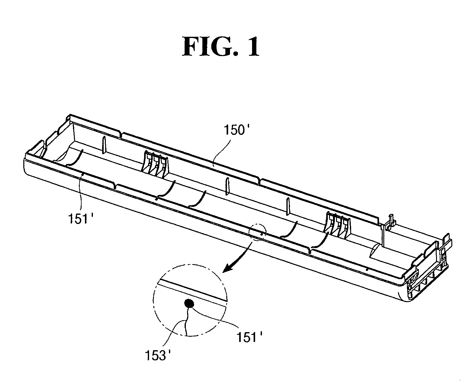
[0012]Accordingly, an object of the present invention is to provide a battery pack that can prevent formation of crack on a case that accommodate bare cells by forming grooves near a pin point gate part so as to distribute stress caused by external impact, and that can prevent an electrolyte leaking out of a bare cell from flowing into a notebook computer through the case.
[0013]According to another object of the present invention, there is to provide a battery pack that can prevent an electrolyte leaking out of a bare cell from flowing into a notebook computer through the case by preventing formation of crack in the case.

Problems solved by technology

However, the battery pack has a problem that brittle deformation such as a crack firstly occurs at a pin point gate part because a surface of the pin point gate part located at an end of a rib is not even compared to a peripheral part, and thus stress is concentrated on the pin point gate part when an impact load is applied to a case.
When the brittle deformation occurs in the case of the battery pack by impact load, there is a problem that an electrolyte leaking out of the bare cell flows along the surface of the case, and eventually flows into inside a notebook computer, thereby damaging the notebook computer, and causing an electrical short.
Further, a separator plate is located on a lower face of the circuit board, and accordingly the electrolyte flowed toward the circuit board does not move to other place, and remains in the circuit board for a long time, thereby allowing damage of the notebook and an electrical short to be accelerated.
Furthermore, there is another problem that the charge / discharge control may not be well performed because of the damage of the circuit board, and fire may be broken out due to an electrical spark.

Method used


Image

  • Battery pack
  • Battery pack
  • Battery pack

Examples


Embodiment Construction

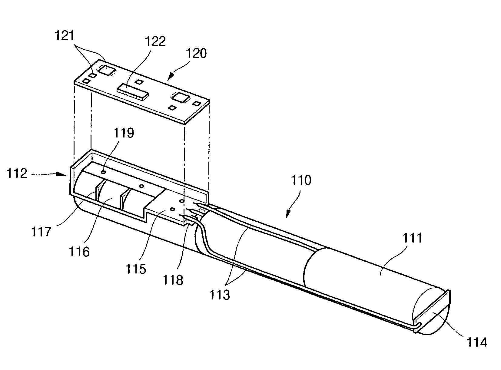
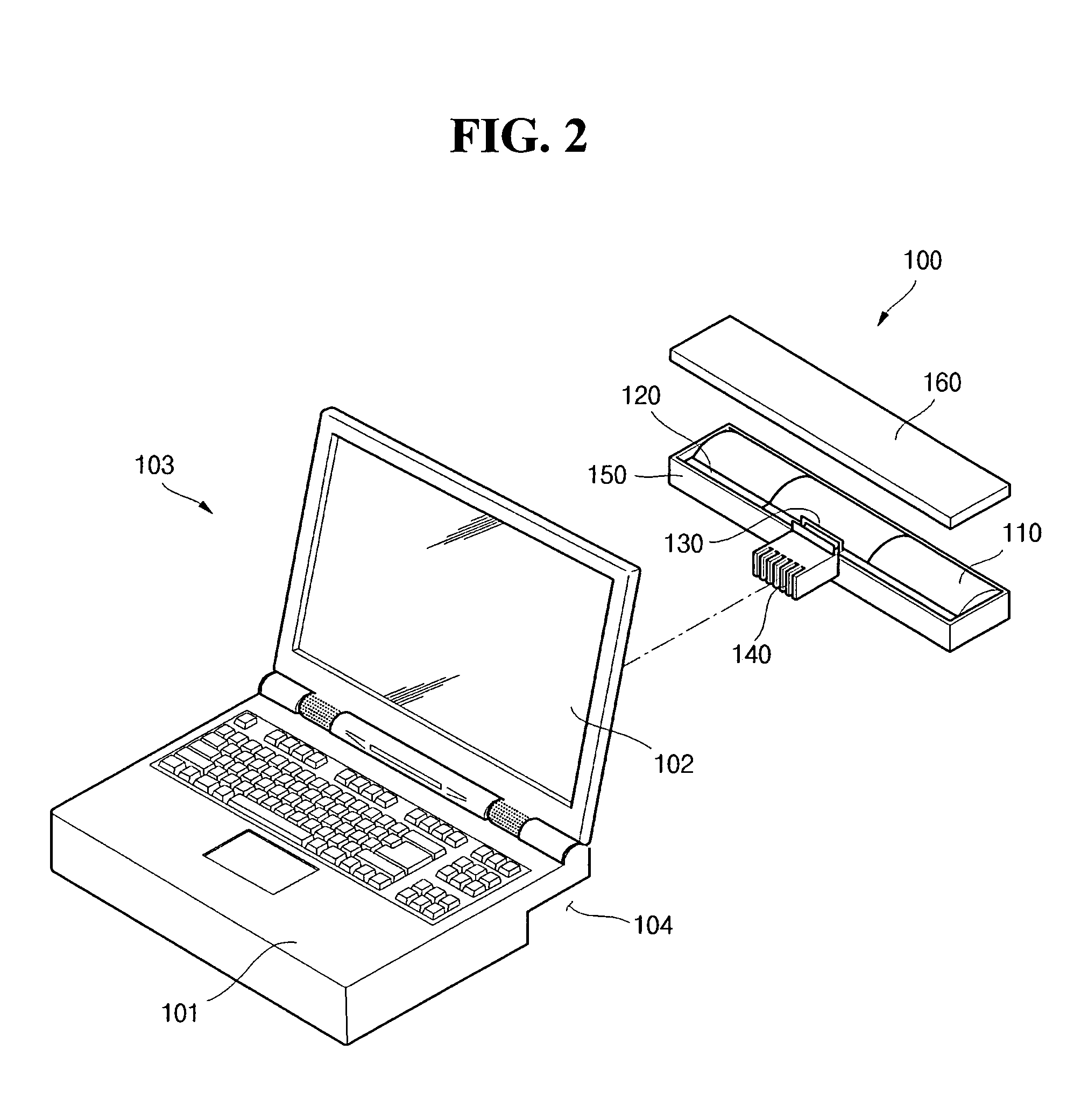
[0027]Hereinafter, preferred embodiments of the present invention will be described in detail with reference to the accompanying drawing. The aspects and features of the present invention and methods for achieving the aspects and features will be apparent by referring to the embodiments to be described in detail with reference to the accompanying drawings. However, the present invention is not limited to the embodiments disclosed hereinafter, but can be implemented in diverse forms. The matters defined in the description, such as the detailed construction and elements, are nothing but specific details provided to assist those of ordinary skill in the art in a comprehensive understanding of the invention, and the present invention is only defined within the scope of the appended claims. In the entire description of the present invention, the same drawing reference numerals are used for the same elements across various figures.

[0028]FIG. 1 is a perspective view illustrating a case of ...


PUM

PropertyMeasurementUnit
distanceaaaaaaaaaa
distanceaaaaaaaaaa
distanceaaaaaaaaaa

Abstract

Disclosed is a battery pack having a case in which a groove is formed near a pin point gate part so as to prevent formation of a crack in the case caused by external impact. The groove distributes stress caused by external impact. By preventing the formation of a crack, an electrolyte leaking out of a bare cell is prevented from flowing into a notebook computer through the crack. The battery pack includes at least one bare cell, a circuit board electrically coupled to the bare cell and a case formed so as to receive the bare cell and the circuit board. The case includes pin point gates formed in the front of the case during an injection molding process and grooves formed near the pin point gates.

Description

CLAIM OF PRIORITY[0001]This application makes reference to, incorporates the same herein, and claims all benefits accruing under 35 U.S.C. §119 from an application earlier filed in the Korean Intellectual Property Office on the 11th of Apr. 2007 and there duly assigned Serial No. 10-2007-0035715.BACKGROUND OF THE INVENTION[0002]1. Field of the Invention[0003]The present invention relates to a battery pack and more particularly, to a battery pack including a case that has a pin point gate part and a groove formed near the pin point gate part. The groove prevents formation of a crack around the pin point gate part by distributing stress applied on the pin point gate part by external impact.[0004]2. Description of the Related Art[0005]Recently, portable electronic devices such as a cellular phone, PDA (Personal Digital Assistants), a camcorder, a notebook computer have been broadly used. These devices have a built-in battery pack so as to operate in the place where an additional power ...

Claims


Application Information

Patent Timeline
Patent Type & Authority Applications(United States)
IPC IPC(8): H01M2/10
CPCH01M10/425H01M2/1055Y02E60/10H01M50/213G06F1/1613G06F1/1635G06F1/1675G06F2200/163
Inventor MOON, DEAYON
Owner SAMSUNG SDI CO LTD
Learn More