Radio Receiver and Radio Transmitter

a radio receiver and radio transmitter technology, applied in the direction of amplitude demodulation, instruments, resonant circuit details, etc., can solve the problems of reducing reception sensitivity, signal noise produced when a radio signal is received, and inability to perform transmission and reception of radio signals, etc., to achieve simple and relatively inexpensive configurations

Inactive Publication Date: 2008-10-16
MURATA MFG CO LTD
View PDF8 Cites 11 Cited by
  • Summary
  • Abstract
  • Description
  • Claims
  • Application Information

AI Technical Summary

Benefits of technology

[0016]To overcome the problems described above, preferred embodiments of the present invention provide a radio receiver and a radio transmitter that compensate for the influence of a frequency drift, while ensuring communication reliability, and that have simple, relatively inexpensive configurations.

Problems solved by technology

Thus, there is a problem in that if the deviation of the intermediate-frequency signal increases, transmission and reception of the radio signal cannot be performed.
In contrast, signal noise that is produced when a radio signal is received increases in proportion as the frequency bandwidth for the radio signal increases.
Thus, a problem occurs in that the reception sensitivity is reduced and communication reliability, such as a BER (Bit Error Rate), decreases.
However, when the oscillator having the temperature compensation function, such as a TCXO, is used, the unit cost of such an oscillator is substantially greater than an oscillator which does not have a temperature compensation function.
Thus, there is a problem in that the overall cost of the entire radio communication system is increased.
Thus, this communication system requires a large, complicated circuit.
Thus, this communication system also requires a large complicated circuit, and has a problem of degradation of communication reliability.
Thus, a new problem arises in that the cost of the entire radio communication system is substantially increased.
However, at the same time, such a circuit is complicated, the number of component parts increases, and the area required on an IC increases.
Thus, a problem arises in that the cost of the entire communication system is increased.

Method used


Image

  • Radio Receiver and Radio Transmitter
  • Radio Receiver and Radio Transmitter
  • Radio Receiver and Radio Transmitter

Examples


Embodiment Construction

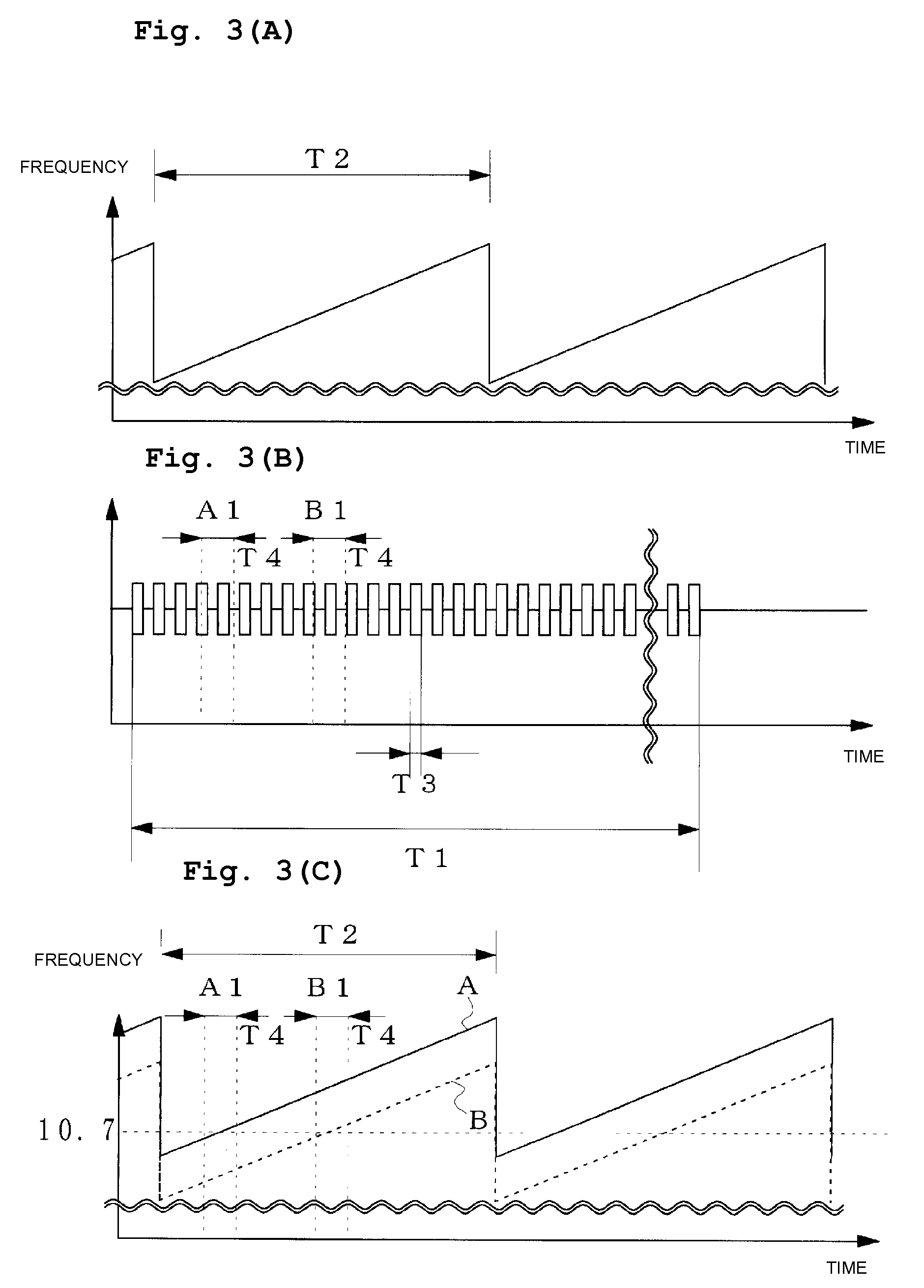
[0045]A first preferred embodiment in which an oscillation frequency of a superheterodyne radio receiver that receives an FSK radio signal is swept will be described.

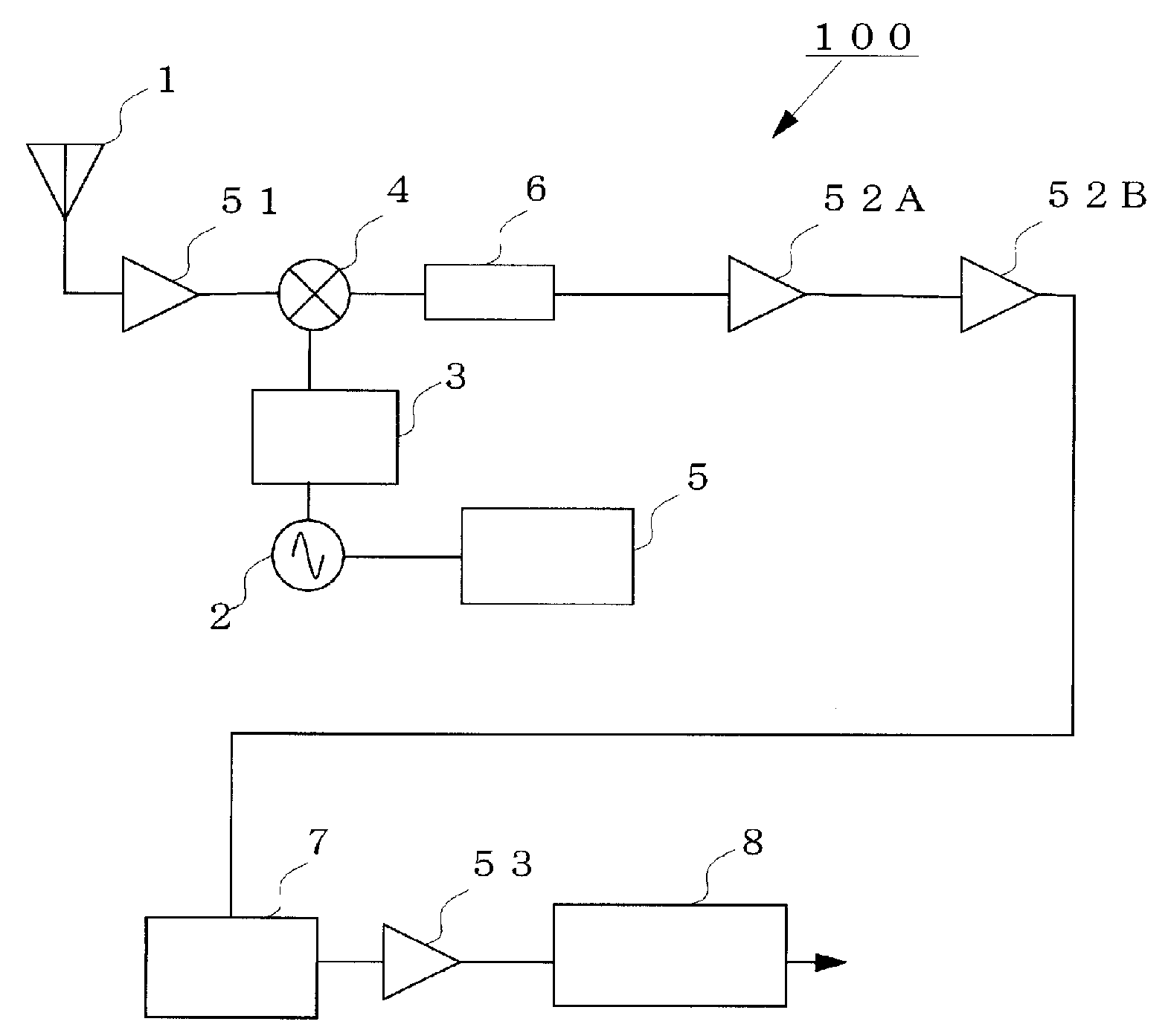
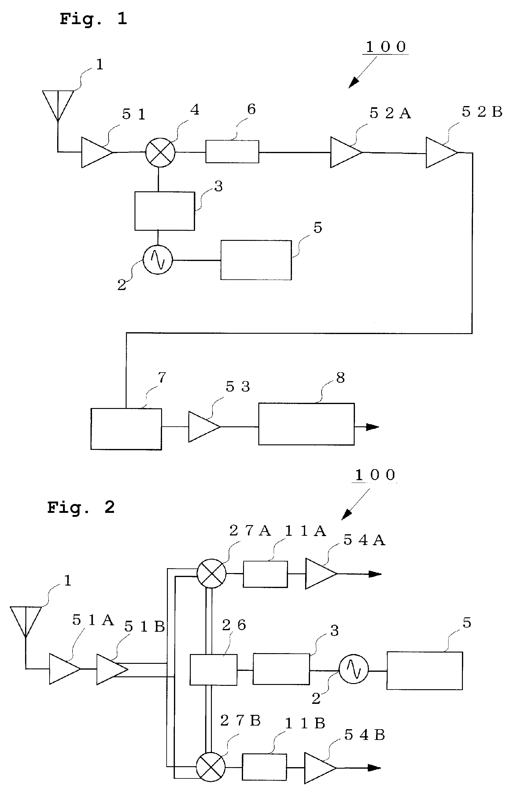
[0046]FIG. 1 is a block diagram showing the configuration of the first preferred embodiment of the present invention.

[0047]In this preferred embodiment, a radio receiver 100 receives from an aerial wire 1 a radio signal having a carrier in the 315 MHz frequency band, and outputs the radio signal to a high-frequency amplifier 51. A frequency multiplier 3 multiplies an oscillation signal of a voltage-controlled 38 MHz oscillator VCXO 2 by eight. The VCXO 2 and the frequency multiplier 3 define a local oscillation circuit. In an ideal state in which no frequency drift occurs and sweep is not performed, when the frequency multiplier 3 multiplies the frequency of the VCXO 2, which is 38.0375 MHz, by eight, a local oscillation signal of 304.3 MHz is acquired. In addition, a mixer circuit 4 mixes this local oscillation signal ...


PUM


Abstract

In a radio receiver including an aerial wire (1) that receives a radio signal in which a transmission signal is superimposed on a carrier, a (VCXO 2) that oscillates a local oscillation signal, a frequency multiplier (3), and a demodulation circuit that demodulates the transmission signal on the basis of the radio signal and the local oscillation signal, an oscillation frequency control circuit that repeatedly sweeps the frequency of the local oscillation signal over a frequency bandwidth that is equal to or more than the width of a frequency drift in a carrier frequency from the aerial wire (1) or over a frequency bandwidth that is equal to or more than the width of a frequency drift in the local oscillation signal is provided.

Description

BACKGROUND OF THE INVENTION[0001]1. Field of the Invention[0002]The present invention relates to radio receivers and radio transmitters that compensate for the influence of frequency drifts in oscillation circuits that generate carriers, local oscillation signals, and other signals.[0003]2. Description of the Related Art[0004]In radio communications, such as a keyless entry system that requires a short time to transmit and receive a control code having a short length, a radio transmitter transmits a radio signal on which information, such as an identification code and a control code that are allocated for each object, is superimposed, and a radio receiver receives the radio signal and demodulates the codes. Then, in accordance with the demodulated codes, a controller authenticates the object and locks / unlocks a door.[0005]In such radio communications, the radio transmitter must include an oscillation circuit that oscillates a high-frequency signal, which functions as a carrier, and ...

Claims


Application Information

Patent Timeline
Patent Type & Authority Applications(United States)
IPC IPC(8): H04B1/04H04L27/00H04B1/26H04B1/30
CPCH03J1/0091H04B1/28H03J7/02H04B1/02H04B1/04H04B1/06
Inventor KATO, AKIRA
Owner MURATA MFG CO LTD
Why Eureka
Try Eureka