Percutaneous access system

a percutaneous access and access system technology, applied in the field of medical technology and medical devices, can solve the problems of soft pu tubing being prone to deformation or compression under resistance, and the difficulty of surgeons

Inactive Publication Date: 2008-10-16
EDWARDS LIFESCIENCES CORP
View PDF9 Cites 20 Cited by
  • Summary
  • Abstract
  • Description
  • Claims
  • Application Information

AI Technical Summary

Benefits of technology

[0011]In one aspect, a cannulation system is provided including a cannula body having a distal end and a first lumen extending therein. The system also includes an introducer configured to be insertably received into the distal end of the cannula body; and a transition device including a first section having an attachment geometry, a second section having a variable external diameter and an inner lumen extending therein. The first section is inserted into the first lumen at the distal end of the...

Problems solved by technology

The soft PU tubing is prone to deformation or compression under resistance, for example when pushing through connective tissue such as might be encountered dur...

Method used


Image

  • Percutaneous access system
  • Percutaneous access system
  • Percutaneous access system

Examples


Embodiment Construction

[0022]The disclosure is now described more fully hereinafter with reference to the accompanying drawings, in which some, but not all embodiments are shown. The disclosure may be embodied in many different forms and should not be construed as limited to the embodiments set forth herein. Like numbers refer to like elements throughout.

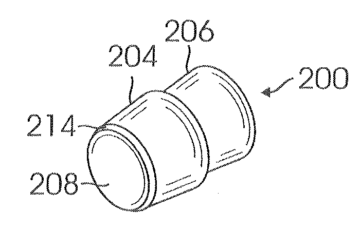
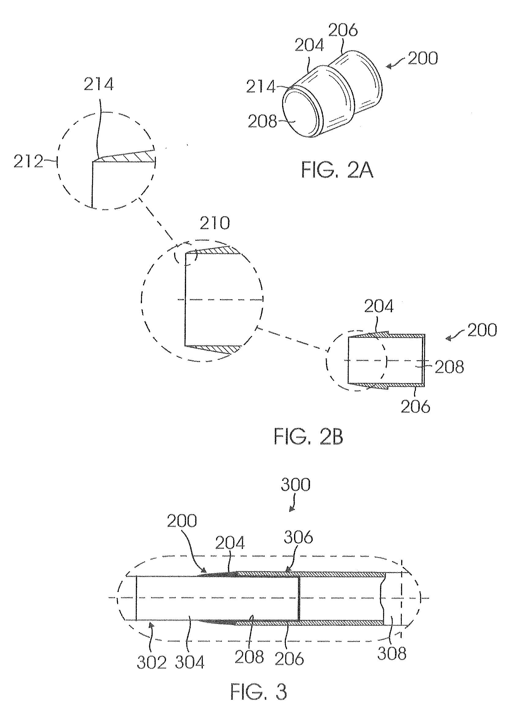
[0023]FIG. 2A is a simplified perspective view of a transition device 200 in accordance with an embodiment of the present invention. As shown in FIG. 2A, transition device 200 is a tubular structure formed as a combination of two external sections: a first section 204 having a first geometry, for example, a variable external diameter and a second section 206 having a second geometry, for example, a substantially constant external diameter. In one embodiment, the substantially constant external diameter is formed with a requisite length and diameter to facilitate attachment to cannula tubing, such as by interference fitting second section 206 into the lume...


PUM


Abstract

A transition device for placement at the opening of the tip of a cannula body for the purpose of controlling the shape of the cannula tip opening under various loads such as might be encountered during device placement.

Description

BACKGROUND[0001]1. Field of the Invention[0002]This invention relates to the field of medical technology and medical devices and more particularly to the process of cannulation of the cardiovascular system to remove or return blood or other fluids through a cannula device.[0003]2. Related Art[0004]The process of cannulation of the cardiovascular system to remove or return blood or other fluids through a cannula device is known. One example, shown in FIG. 1A, is a venous cannulation system 100, including a cannula 102 and an introducer 104 designed to remove blood from the venous side of the circulatory system during a surgical procedure that requires cardiopulmonary bypass (CPB).[0005]Cannula 102 should preferably be deflectable at its distal end 106 to permit proper positioning of distal end 106 of cannula 102 including introducer 104 within the femoral vein.[0006]Frequently, the distal end or tip 106 of cannula 102 is made from a soft material, such as soft Polyurethane (PU) tubin...

Claims


Application Information

Patent Timeline
IPC IPC(8): A61M37/00A61M39/10A61M25/18A61M39/00A61M25/16
CPCA61B17/3415A61M25/0069A61M1/3659
Inventor HOFFMAN, BRENTDUMMER, C. WADEMITCHELL, SEAN
Owner EDWARDS LIFESCIENCES CORP
Why Eureka
Try Eureka