Intravenous apparatus and method

a technology of intravenous apparatus and a catheter, which is applied in the field of intravenous apparatus and method, can solve the problems of infiltration, potential serious health condition known as infiltration, and complications for patients receiving iv fluid therapy, and achieve the effect of preventing damage or dislocation

Inactive Publication Date: 2013-12-19
SMART IV
View PDF6 Cites 19 Cited by
  • Summary
  • Abstract
  • Description
  • Claims
  • Application Information

AI Technical Summary

Benefits of technology

[0011]A sharp, pointed rod or trocar fits inside a cannula or the soft catheter tube and the sharp point pierces the skin and is directed into a predetermined vein of the patient by the medical technician or doctor. The trocar is then withdrawn. A sensor generally located within the hollow tubing of the flexible or rigid cannula detects a drop in the impedance as blood flows across the surface of the cannula. The sensor is usually embedded within the polymer material of the cannula that protects it from being damaged when it pierces the skin and enters into the patient's vein. The sensors and the wire connections are generally embedded in the polymer material during the manufacturing and extrusion process or later after the extrusion process the sensors and wire are deposited on the cannula surface and properly covered by a thin skin material to prevent damage or dislocation from the cannula along with any wire connections extending back to a module for processing the sensed signal. The sensor(s) then send an electrical signal back to the module for either a visual display or audible sound indication of proper cannula insertion within the patient's vein. The module may take several shapes and have a predetermined thickness and shape in order to house a power source, processing electronics, a soft button switch or similar device for initiating the device when taken out of its package for the first time to be used on a patient. The processing electronics in the module receives the input signal from the sensor(s) and then generates an output signal that fires a light emitting diode (LED) display or in addition, fires a piezo-electric buzzer horn along with the light indication so the medical technician gets both a light and a sound indication of proper insertion of the cannula into a patient's vein.

Problems solved by technology

Due to the different skill levels of the medical personnel inserting the IV cannula into the peripheral vein of a patient's hand or arm, complications sometimes develop in a number of the patients receiving IV fluid therapy from infiltration.
This is a condition where through improper insertion or withdrawal of the cannula either into or from a peripheral vein, respectfully, results in IV fluids leaking into the surrounding tissues around the vein causing a potential serious health condition known as infiltration.
If the cannula is not sited properly or the vein is missed or even pierced where the cannula goes through the vein and enters into the surrounding subcutaneous tissue rather than remaining in the vein, complications may develop for the patient receiving the IV fluid therapy.
Many serious complications can result from improper cannula insertion into the vein.
The potential complications include edema causing tissue damage or may even include necrosis depending on the medication or fluid being infused.
The leakage of high osmotic solutions or chemotherapy fluids can result in significant tissue destruction or other complications.
However, due to human error, mistakes are bound to be made while inserting the cannula into a vein or the vein is missed altogether during the initial insertion of the needle / cannula.
However, none of these prior art patents teach a highly reliable portable apparatus and method of guiding a catheter into a vein and then detecting the proper insertion of the IV cannula of the catheter during its insertion into the patient's peripheral vein by providing a feedback signal either visual or audible for the intern, nurse or EMT starting the IV therapy.
Most of these prior art infusion detection systems referred to above while doing a good job in detecting problems once the IV therapy begins, the prior art systems do not monitor the initial insertion of the IV cannula into the vein to make sure the cannula is properly inserted into the patient's vein.
In short, all of these systems are rather complicated and therefore require expensive pieces of equipment that are not necessarily readily available to paramedics or EMTs in the field who must start the IV therapy to an injured patient at an accident scene or even immediately available to the nurses, interns or EMTs even in a hospital emergency room setting.

Method used


Image

  • Intravenous apparatus and method
  • Intravenous apparatus and method
  • Intravenous apparatus and method

Examples


first embodiment

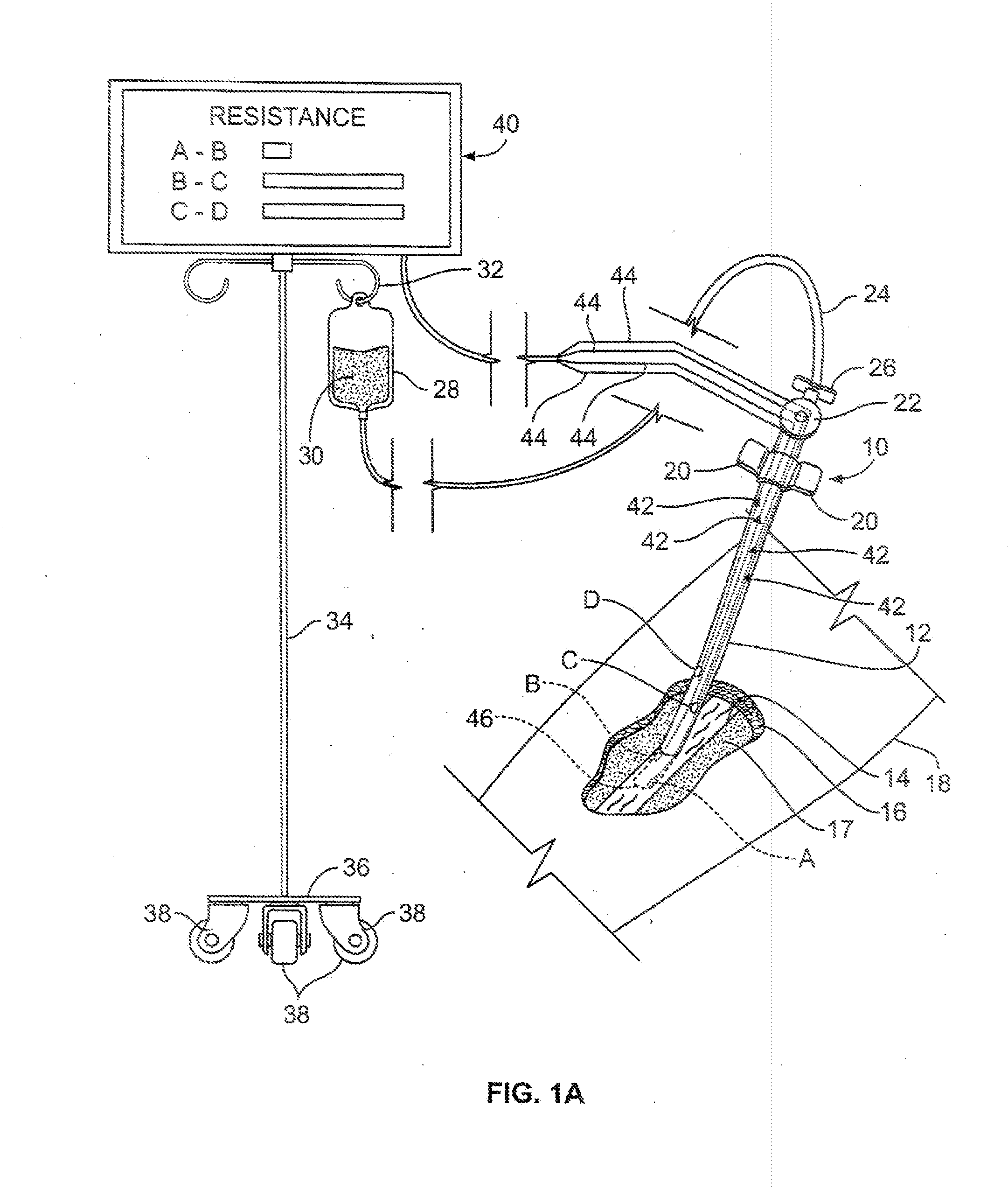
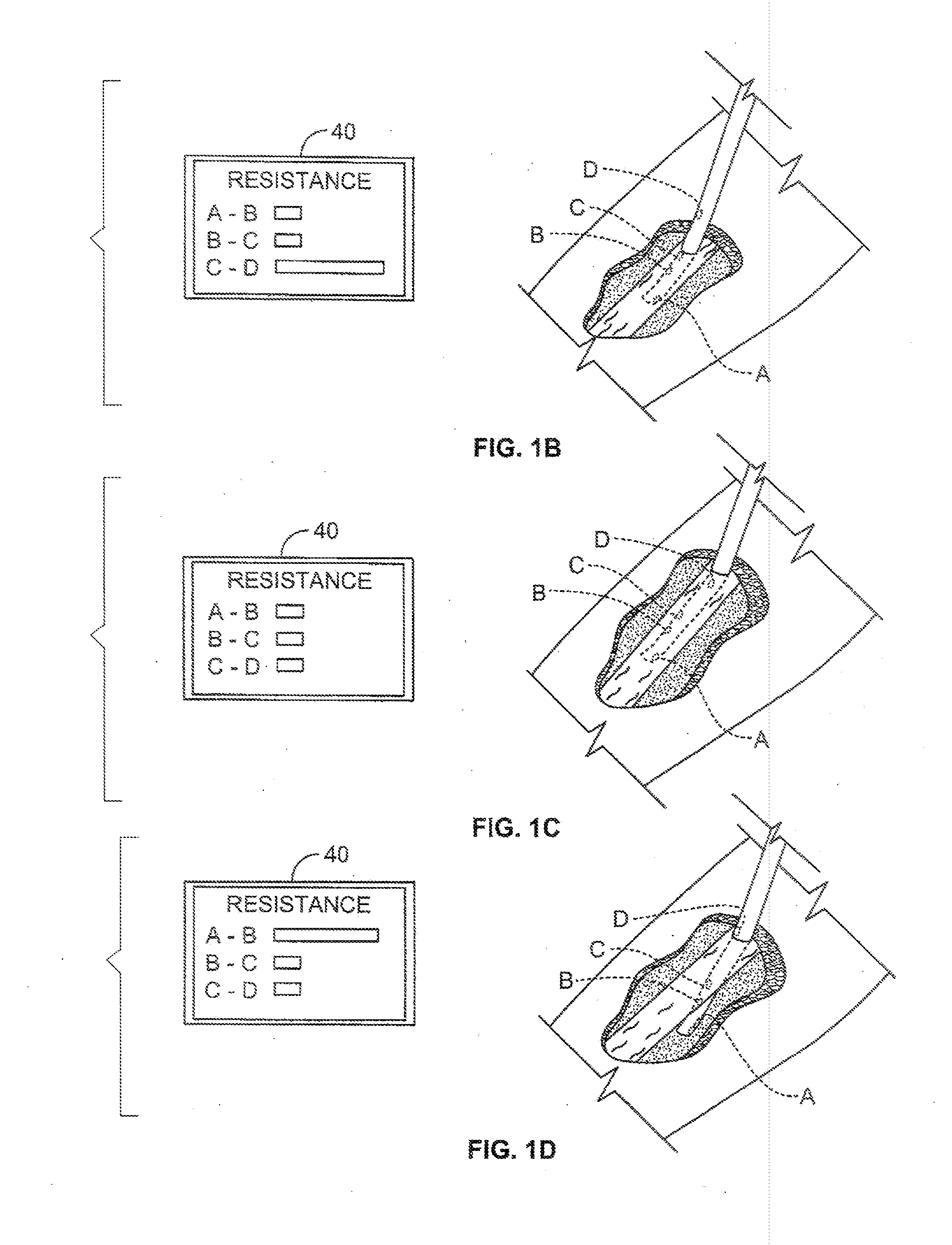
[0048]As mentioned above, the first embodiment is illustrated in FIGS. 1A-1D and includes a catheter 10 constructed in accordance with the present invention. The typical catheter 10 consists of a short polymer tubing (a few centimeters long) inserted through the skin into a peripheral vein 14 (any vein generally not inside the chest or abdomen). This is usually in the form of a flexible cannula 12 over-needle device, in which a flexible plastic cannula 12 comes mounted on a metal trocar (needle and trocar not shown as already withdrawn from cannula 12). Once the tip of the needle and cannula 12 are located within the vein 14 the trocar is withdrawn and discarded. The cannula 12 is further advanced inside the vein to an appropriate position and then secured with medical tap or the like over a pair of plastic wings 20 secured to the tubing near a port or hub 22. An IV line 24 connects to the port or hub 22 through a male fluid input 26 that is inserted into the IV line 24. The IV line...

second embodiment

[0053]Turning now to FIG. 2A, an IV cannula with a single conductive spot or sensor 56 near the tip or distal end 46, with a conductive trace 44 running back to the hub 22, and thus to the sensing module 48 which is attached to the patient much like a conductive EEG pad. In this second embodiment, a 50 kHz signal (or other suitable AC freq) is transmitted and received through the cannula at a very low current of 500 μA and voltage by the sensing module 48. The signal impedance will vary significantly when the cannula 12 is in the vein / bloodstream vs insertion just under the skin 18 but not within the vein 14. The sensing module 48 further includes a soft switch or dome switch 50 to initiate the smart IV catheter when it is first taken from its package. Or the sensing module 48 is initiated when the adhesive cover is removed when the catheter is taken out of its packaging and placed onto the forearm 18. There is also an LED 52 and audible piezo horn 54 mounted within the sensing modu...

fourth embodiment

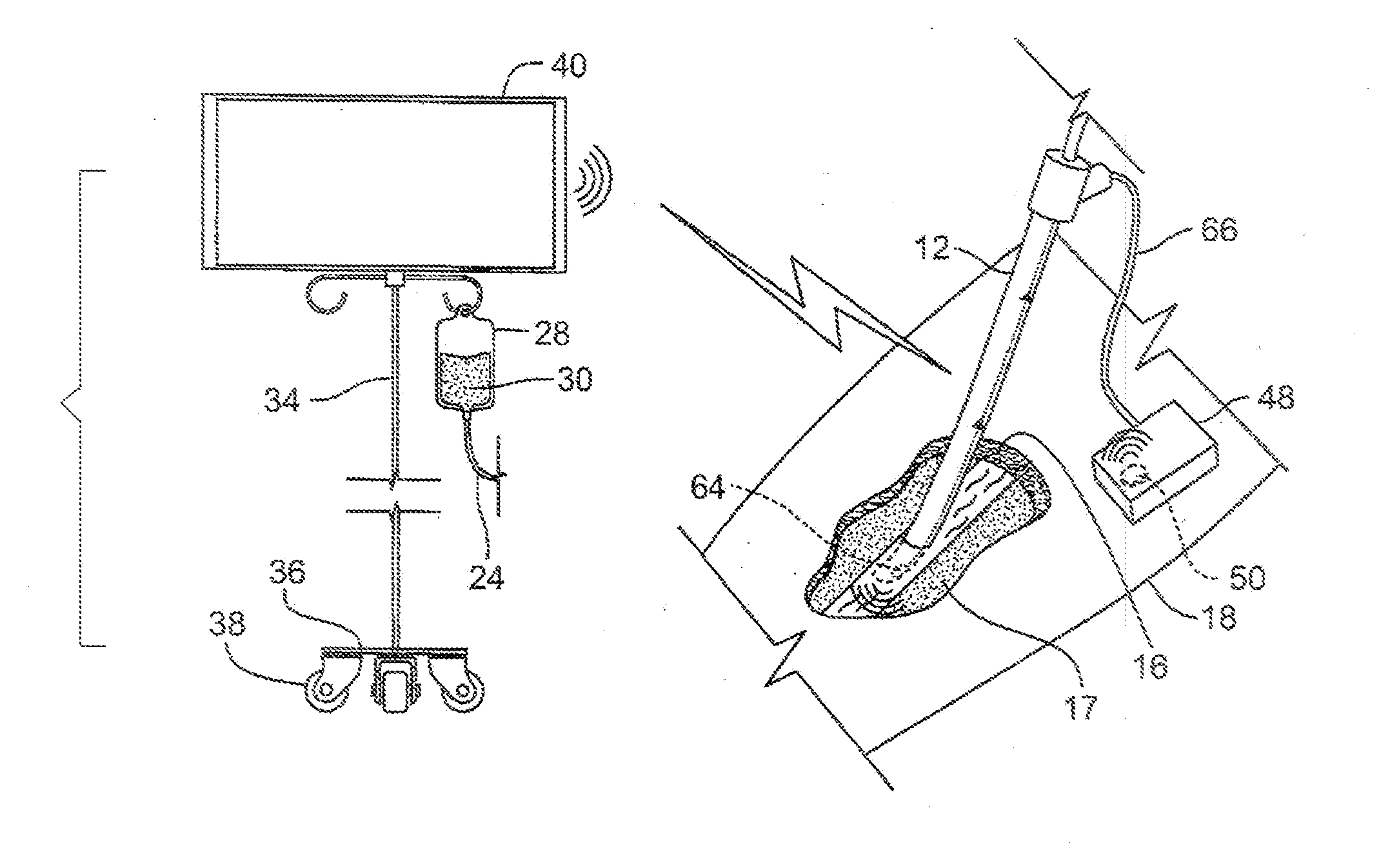
[0062]In FIGS. 5A-B, a fourth embodiment shows the use of an acoustical signature for the apparatus and method to continuously monitor that the cannula 12 is remaining properly inserted within the vein 14 in accordance with the present invention. The cannula 12 includes an acoustical transducer 64 of a broadband 25 to 50 MHz type well known in the art such as the medical transducers manufactured and sold by General Electric Company of Schenectady, N.Y. The transducer 64 is placed near the tip of the cannula 12 such that a large amplitude echo signal from the transducer 64 is continuously monitored to indicate the correct tip placement of the cannula tubing 12 within the vein 14. If suddenly a smaller amplitude echo signal from the transducer 64 is detected then this provides an indication that the tip of the cannula 12 of the catheter 10 is withdrawing from the vein 14 into the subcutaneous tissue surrounding the vein.

[0063]Most high frequency transducers for medical applications ar...


PUM


Abstract

A method and apparatus for inserting and monitoring the placement of a cannula tip within a peripheral vein of a human body where the cannula includes a sensor located at predetermined location and mounted on the cannula for sensing the biological material of the body to guide the insertion of the cannula tip into the vein and alerts to the withdrawal of the cannula tip from the vein in the body.

Description

FIELD OF INVENTION[0001]This invention relates to an intravenous apparatus and method, and more particular, to an intelligent intravenous apparatus and method for detecting a problem with a catheter tip placement or withdrawal in and from a vein for infusion of intravenous (IV) fluids.BACKGROUND OF THE INVENTION[0002]Certain emergency circumstances demand immediate intravenous therapy for patients facing life threatening loss of bodily fluids due to accidents or other critical care applications found in emergency centers or in critical care facilities of a hospital. IV therapy requires the infusion of liquid substances directly into a vein of the patient. Typically, IV fluids in a bag suspended from a IV pole employing a drip chamber that is connected to a peripheral IV line which consists of a short catheter inserted through the skin into a peripheral vein outside of the chest or abdomen. This is usually in the form of a cannula-over-needle apparatus, in which a flexible plastic or...

Claims


Application Information

Patent Timeline
Patent Type & Authority Applications(United States)
IPC IPC(8): A61M5/168A61B5/05A61B5/053A61B5/00
CPCA61M5/158A61M2005/1588A61M2205/3561A61M2205/3584A61M2205/3592
Inventor HANN, LENN
Owner SMART IV
Why Eureka
Try Eureka