Eureka AIR delivers breakthrough ideas for toughest innovation challenges, trusted by R&D personnel around the world.

Cannula tip for a cardiac assist device

a technology of cannula and cardiac assist device, which is applied in the direction of heart stimulators, other blood circulation devices, therapy, etc., can solve the problems of sudden decrease in blood pressure, possible death, and “suction condition”, and achieve the effect of preventing the formation of blood clots

Inactive Publication Date: 2007-03-01
HITMAC USA +1
View PDF10 Cites 19 Cited by
  • Summary
  • Abstract
  • Description
  • Claims
  • Application Information

AI Technical Summary

Benefits of technology

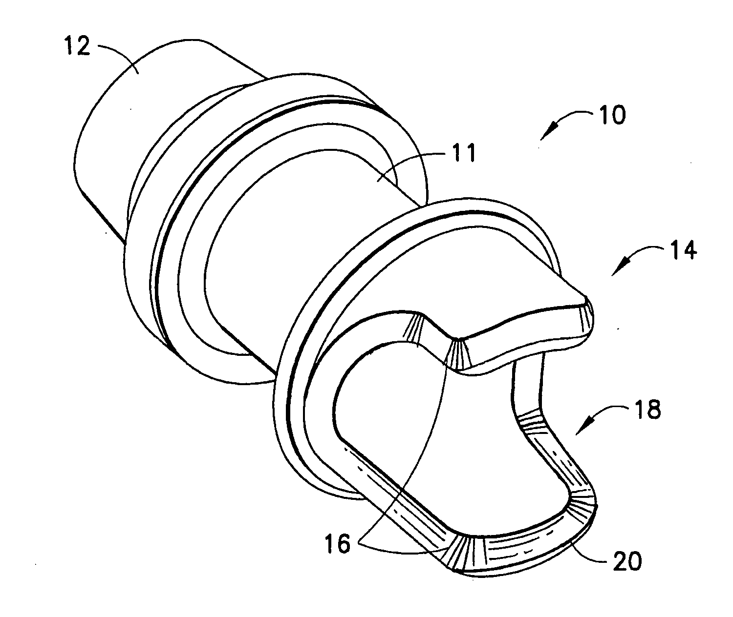
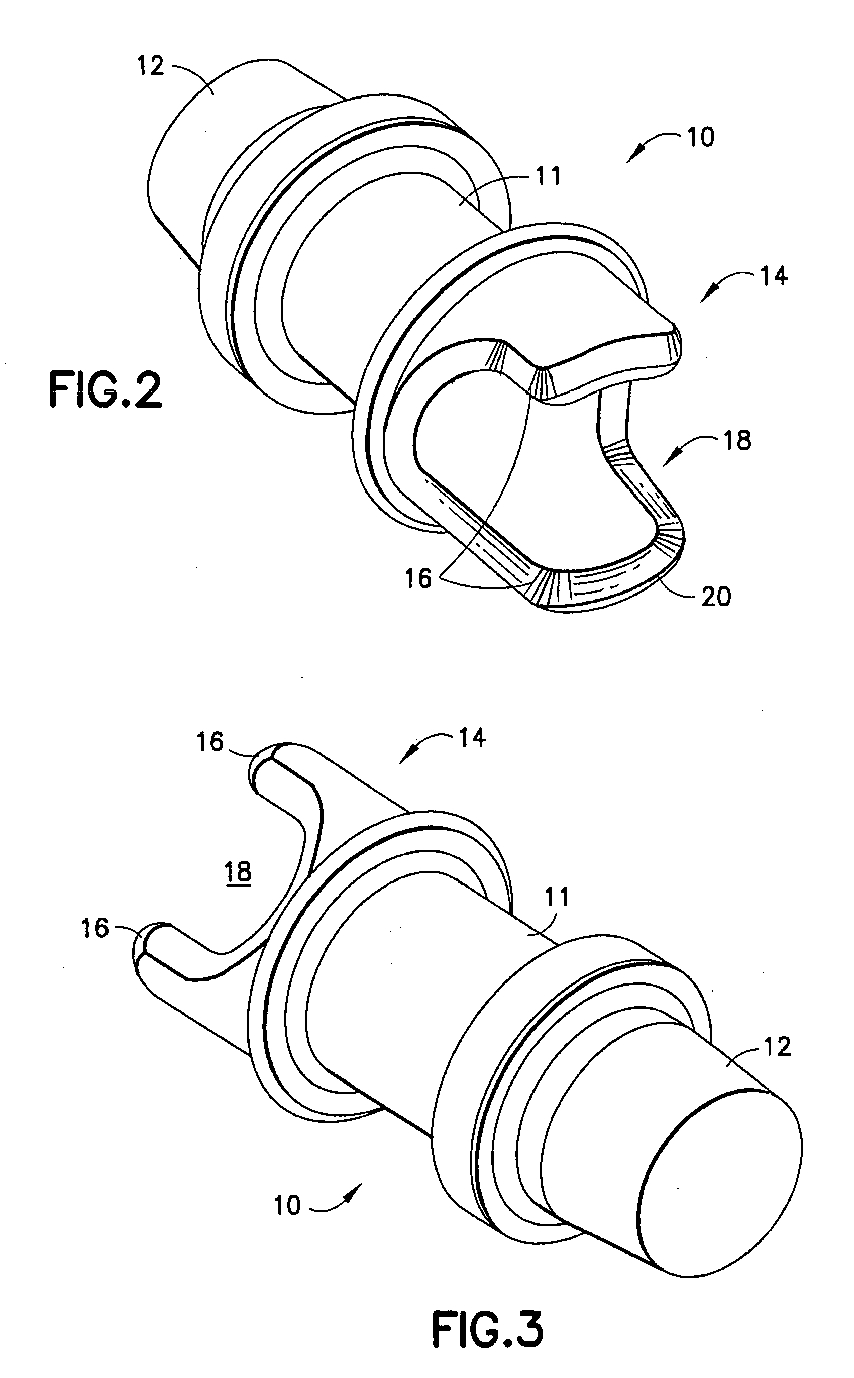
[0017] The cannula tip may comprise one of a biocompatible hard plastic, a biocompatible carbon material, and a biocompatible metal. For example, the cannula tip may comprise one of polyvinyl or polyurethane. Alternatively, the cannula tip may comprise a titanium alloy. In an embodiment where the cannula tip is comprised of titanium alloy, the cannula tip may be adapted for use with one of a long term implantable left ventricular assist device or a long term implantable right ventricular assist device. The titanium alloy acts to prevent the formation of blood clots on the inlet portion.

Problems solved by technology

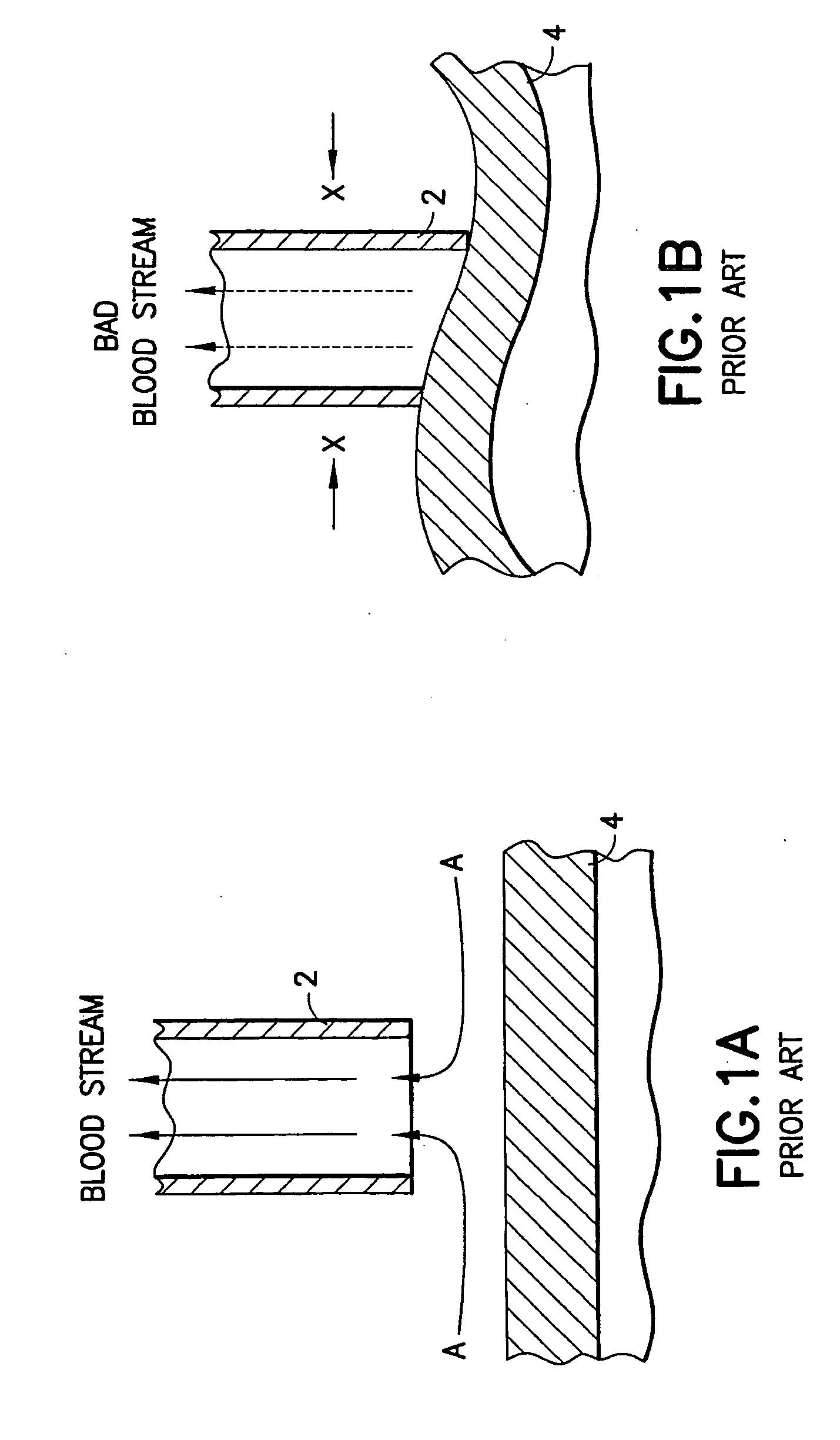
One problem associated with an implanted cardiac assist device is decreased pump flow volume which may result when the inflow cannula tip becomes attached to the ventricle wall resulting in a “suction condition”.
In addition to decreasing the pump flow volume, such a suction condition will also limit the output of the natural heart, leading to sudden decrease in blood pressure, blood circulatory failure, and possible death.
Anatomically there is not enough space available at this location between the right ventricular wall and the septum.
This suction condition may be caused by improper positioning of the cannula tip, excessive pump flow volume, outside pressure of the heart, etc.
A further problem associated with implantable cardiac assist devices is platelet adhesion on the inflow cannula tip, leading to the clots which reduce and ultimately prohibit blood flow.

Method used


Image

  • Cannula tip for a cardiac assist device
  • Cannula tip for a cardiac assist device
  • Cannula tip for a cardiac assist device

Examples


Embodiment Construction

[0030] The ensuing detailed description provides exemplary embodiments only, and is not intended to limit the scope, applicability, or configuration of the invention. Rather, the ensuing detailed description of the exemplary embodiments will provide those skilled in the art with an enabling description for implementing an embodiment of the invention. It should be understood that various changes may be made in the function and arrangement of elements without departing from the spirit and scope of the invention as set forth in the appended claims.

[0031] The present invention relates to a cannula tip for long term use at the inflow of an implantable blood pump that is designed to prevent the occurrence of a suction condition and the adhesion of platelets. Particular example embodiments of the inventive inflow cannula tip are useful for a right ventricular assist device. Embodiments of the inventive inflow cannula tip may also be used with a left ventricular assist device.

[0032]FIGS. ...


PUM


Abstract

The present invention provides an inflow cannula tip that is shaped to prevent suction with the ventricular wall and adapted to prevent platelet adhesion. In particular, the inlet portion of the cannula tip comprises two projections extending from the cylindrical body of the cannula tip with gaps between the projections. The projections may have beveled edges. The inlet portion of the cannula tip can accept blood flow from either the gaps in the side or from the bottom of the tip. Even if the edge of the cannula tip is close to or even touching ventricle wall, a suction condition will not result, as blood is allowed to flow through the gaps between the projections.

Description

[0001] This application is a continuation-in-part of U.S. patent application Ser. No. 10 / 655,489 filed on Sep. 3, 2003, which claims the benefit of U.S. provisional patent application No. 60 / 409,885 filed on Sep. 10, 2002, which is incorporated herein and made a part hereof by reference.BACKGROUND OF THE INVENTION [0002] The present invention relates to the field of cardiac assist devices, such as blood pumps and the like. More specifically, the present invention relates to a cannula tip for use at the inflow of a blood pump that is designed to avoid the creation of a suction condition. [0003] Bypass type cardiac assist devices are used frequently in advanced stages of heart failure to assist the failing human heart. It is typical for such devices to be used as left ventricular assist devices (LVAS) or right ventricular assist devices (RVAS). [0004] Approximately 30% of the deaths of LVAS patients are the result of excessive venous pressure, increase in the hepatic portal vein press...

Claims


Application Information

Patent Timeline
IPC IPC(8): A61N1/362A61B17/00A61B17/34A61M1/12A61M1/36
CPCA61B17/3421A61B2017/00243A61M1/1008A61M1/3659A61M1/122A61M1/12
Inventor NOSE, YUKIHIKOSHINOHARA, TOSHIYUKIWATANABE, KUNIYOSHIMOTOMURA, TADASHI
Owner HITMAC USA
Why Eureka
Eureka Blog
Learn More