Cannula tip for use with a vad

a technology of cannula and vad, which is applied in the field of cannula, can solve the problems of significant engineering challenge, lack of pumping capacity of the heart of a human or other mammalian subject to meet the needs of the body, etc., and achieve the effects of low flow resistance, minimal damage to the blood, and stable us

Inactive Publication Date: 2010-01-28
HEARTWARE INC
View PDF23 Cites 18 Cited by
  • Summary
  • Abstract
  • Description
  • Claims
  • Application Information

AI Technical Summary

Benefits of technology

[0007]As further discussed below, certain embodiments of the cannula according to this aspect of the invention provide a desirable combination of low flow resistance, stability in use, minimal damage to the blood and other desirable properties.
[0008]Another aspect of the invention also provides a cannula for use with a blood circulation device. The cannula according to this aspect of the invention desirably has a longitudinal axis and proximal and distal directions along the axis. The cannula according to this aspect of the invention desirably includes a proximal portion having a wall extending around the longitudinal axis and having outer and inner faces, said inner face defining a bore, as well as a distal portion having one or more openings communicating with the bore of the proximal portion. The cannula according to this aspect of the invention preferably has ports extending through the wall of the proximal portion and communicating with the bore in the proximal portion. The ports preferably have aggregate resistance to fluid flow which is substantial in comparison to the aggregate fluid flow resistance of the openings. In a method according to yet another aspect of the invention, the cannula is positioned to extend through a valve of the circulatory system of a mammalian subject such as a human, and blood is supplied to the bore. A substantial portion of the blood, and desirably a majority of the blood passes out of the cannula through the opening. However, some of the blood passes out of the cannula through the ports. As further discussed below, this flow of blood can minimize contact of the cannula with the valve, and thus minimize injury to the valve.

Problems solved by technology

In certain disease states, the heart of a human or other mammalian subject lacks sufficient pumping capacity to meet the needs of the body.
All of these factors, taken together, present a significant engineering challenge.

Method used


Image

  • Cannula tip for use with a vad
  • Cannula tip for use with a vad
  • Cannula tip for use with a vad

Examples


Embodiment Construction

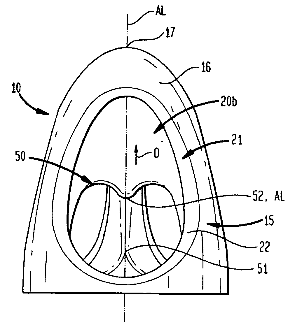
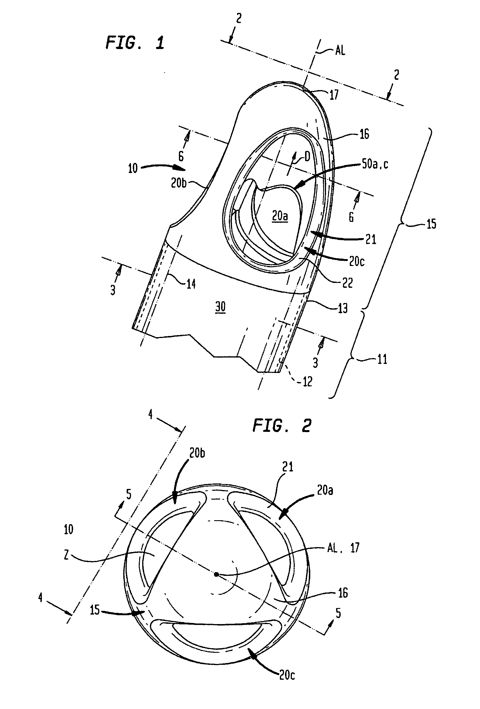
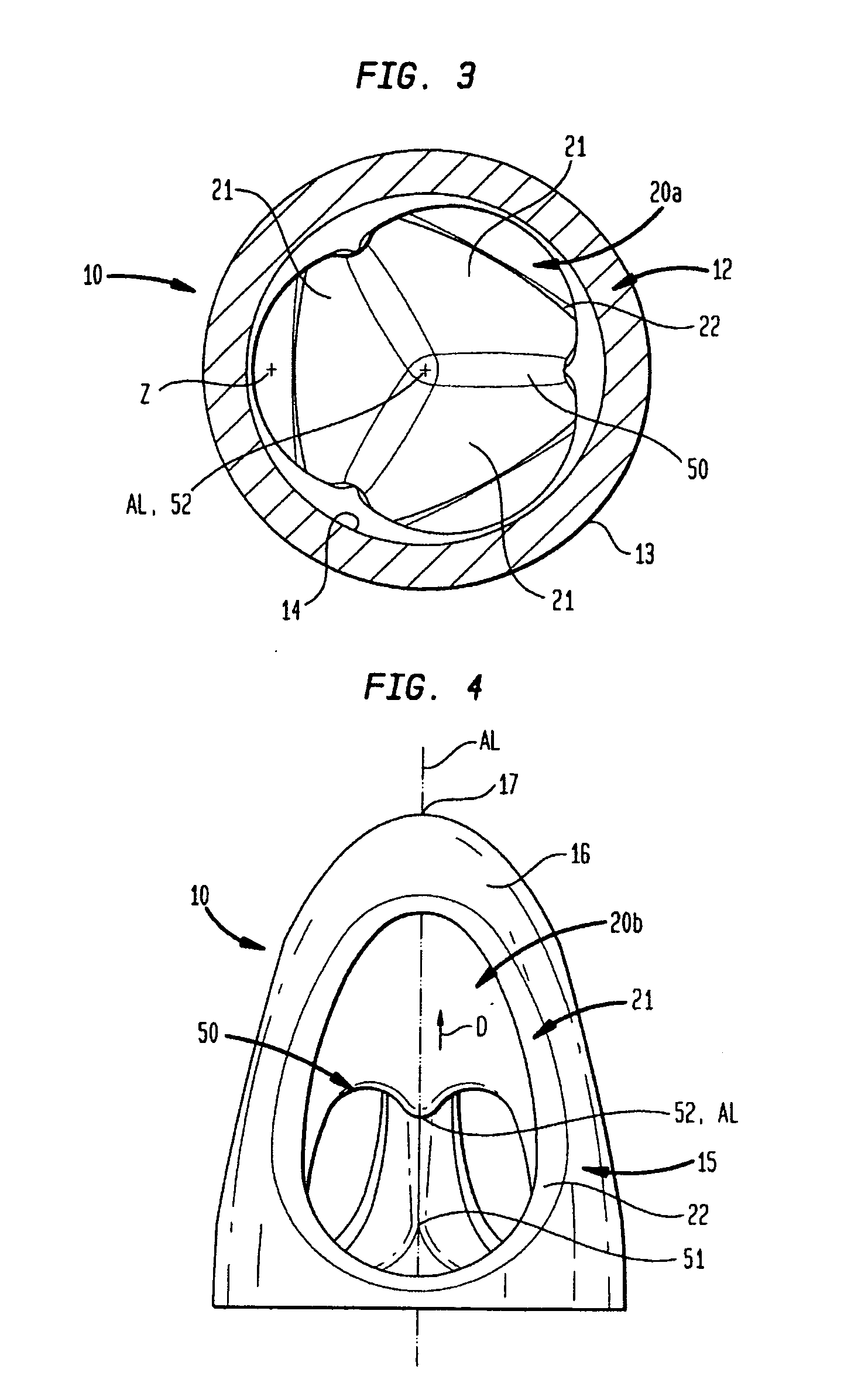
[0022]Referring to FIGS. 1-7, one embodiment of a cannula 10 extends generally along a longitudinal axis AL. The directions along the longitudinal axis are referred to herein as proximal and distal directions. As used herein, the distal direction is the direction away from the end of the cannula which will be attached to the VAD in service, and toward the end of the cannula which will be remote from the VAD in service. For example, in the assembly of FIG. 7, a VAD 101 has an intake 103, a discharge 105 and one or more internal pumping elements (not shown) arranged to impel blood taken in through intake 103 out through discharge 105. One cannula 10A has a proximal end 111 connected to the intake 103 of the VAD and has a distal end or distal-most point 17 remote from the VAD. Another cannula 10B has its proximal end 111 connected to the discharge 105 of the VAD and has a distal end 17 remote from the VAD. In each cannula 10, direction D is the direction away from the proximal end 111....


PUM


Abstract

In one embodiment of the present invention, a cannula for use with a blood circulation device may include the cannula having a longitudinal axis and proximal and distal directions along the longitudinal axis. The cannula may also include a proximal portion having a wall extending around the longitudinal axis and having outer and inner faces, the inner face may define a bore, the proximal portion may have dimensions transverse to the longitudinal axis, and the dimensions may be constant in the proximal and distal directions. Also, the cannula may have a distal portion having an outer face, continuous with the outer face of the proximal portion. The outer face of the distal portion may extend around and along the longitudinal axis, and the outer face of the distal portion may taper distally toward the longitudinal axis. The distal portion may include at least two openings extending from the outer face of the distal portion, which may merge with one another within the distal portion. Then, the openings may communicate with the bore of the proximal portion. One type of blood circulation device may be a ventricular assist device.

Description

BACKGROUND OF THE INVENTION[0001]The present invention relates generally to a cannula which may be used, in some embodiments, with a Ventricular Assist Device (“VAD”).[0002]In certain disease states, the heart of a human or other mammalian subject lacks sufficient pumping capacity to meet the needs of the body. This inadequacy can be alleviated by providing a mechanical pump referred to as a Ventricular Assist Device (“VAD”) to supplement the pumping action of the heart. The intake of the VAD may be equipped with an intake cannula having an interior bore. The VAD and intake cannula may be positioned such that at least a portion of the intake cannula is positioned within a ventricle or atrium. This portion of the intake cannula, typically at or near an end of the cannula, includes an intake region where the interior bore of the cannula communicates with the surroundings. Thus, the VAD can take in blood from within the ventricle.[0003]The discharge of a VAD may be connected to the int...

Claims


Application Information

Patent Timeline
Patent Type & Authority Applications(United States)
IPC IPC(8): A61M25/00A61M1/10A61M60/178A61M60/216A61M60/857
CPCA61M1/3653A61M25/0068A61M1/3659A61M1/1008A61M1/122A61M25/0069A61M60/857A61M60/148A61M60/216A61M60/178A61B17/34
Inventor SCHIMA, HEINRICHSTOIBER, MARTINWIESELTHALER, GEORGEDECKERT, ZENO
Owner HEARTWARE INC
Why Eureka
Try Eureka