
Stent with unconnected stent segments

Inactive Publication Date: 2008-10-16
BOSTON SCI SCIMED INC
View PDF12 Cites 33 Cited by
  • Summary
  • Abstract
  • Description
  • Claims
  • Application Information

AI Technical Summary

Benefits of technology

[0008]The present invention seeks to address these objectives by providing a stent comprising individual expandable stent segments not connected to each other whose design parameters can be readily varied along the length of the stent. Also, since the stent segments are unconnected, deliverability of the stent is increased.

Problems solved by technology

In part because of current methods of manufacture, it is difficult to make a stent having non-uniform design parameters along its length, as opposed to uniform design parameters along its length.

Method used


Image

  • Stent with unconnected stent segments
  • Stent with unconnected stent segments
  • Stent with unconnected stent segments

Examples


Embodiment Construction

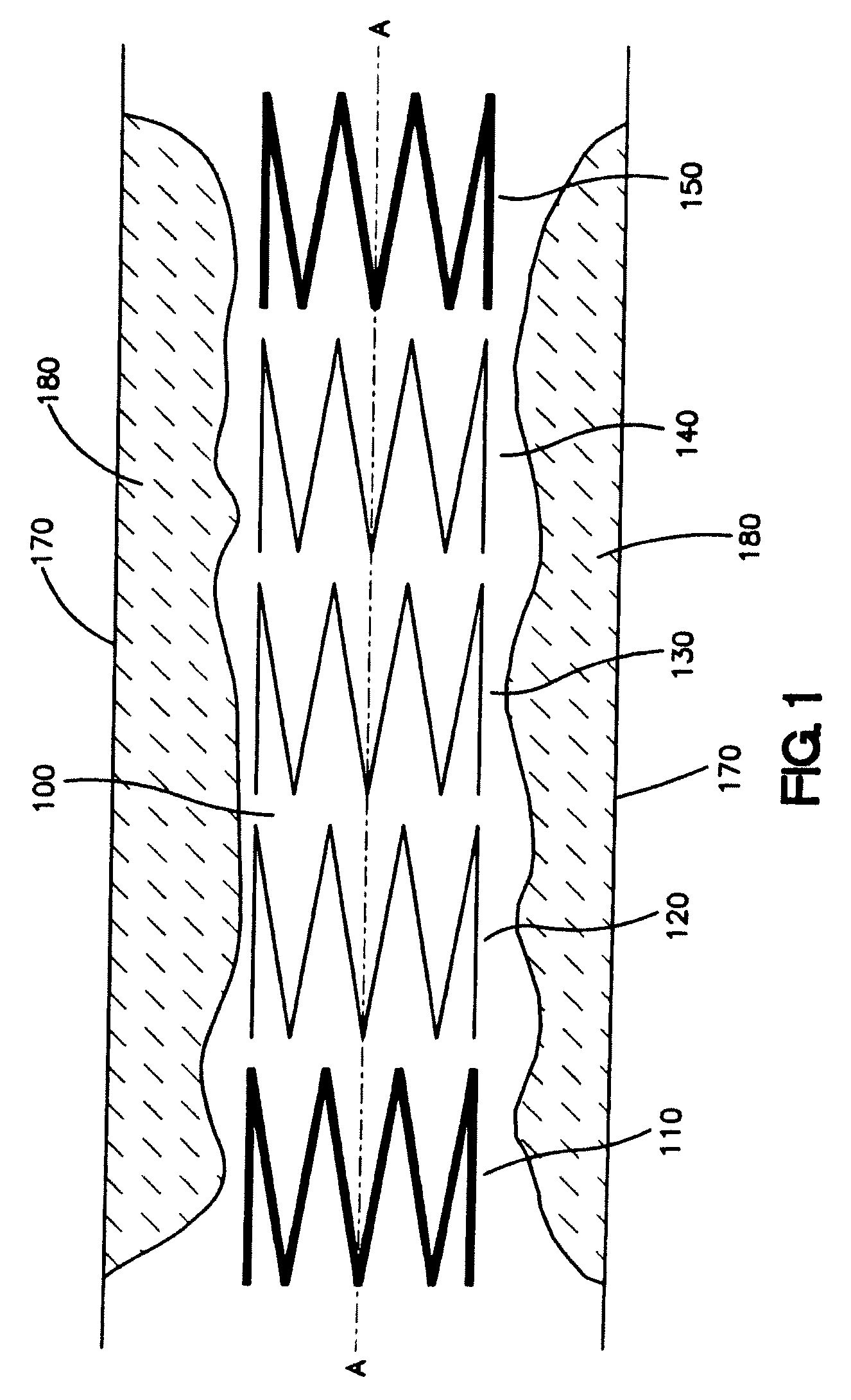
[0032]In one embodiment, the unconnected stent segments comprising a stent may be made of different materials. In the exemplary embodiment depicted in FIG. 1, stent 100 is shown as delivered within body lumen 170, and adjacent to obstruction 180. The portion of body lumen 170 in the vicinity of delivered stent 100 can be called the “stented area.” Stent 100 comprises stent segments such as stent segments 110, 120, 130, 140, and 150 that comprise different materials and are not connected to each other. In alternative embodiments some or all the segments can be connected. Stent 100 has a longitudinal axis A-A. In a preferred embodiment, at least one of stent segments 110, 120, 130, 140, and 150 comprises a different material from at least one other of stent segments 110, 120, 130, 140, and 150. For example, stent segment 110 may comprise platinum or a platinum alloy, and stent segment 120 may comprise stainless steel. Stent segment 130 may comprise a material having a certain weight p...


PUM


Abstract

This invention generally relates to stents, such as intravascular stents. More particularly, the invention is directed to stents comprising expandable stent segments, such as unconnected expandable stent segments. The invention is also directed to methods for making such stents.

Description

CROSS-REFERENCE TO RELATED APPLICATIONS[0001]This application claims the benefit of U.S. Provisional Application No. 60 / 910,698, filed on Apr. 9, 2007, the entire contents of which are incorporated herein by reference.FIELD OF THE INVENTION[0002]This invention generally relates to stents, such as intravascular stents. More particularly, the invention is directed to stents comprising expandable stent segments, such as unconnected expandable stent segments. The invention is also directed to methods for making such stents.BACKGROUND OF THE INVENTION[0003]Stents are used to treat a variety of medical conditions. In blood vessels, they have been used to treat, e.g., stenoses and aneurysms. They are also used to treat or correct conditions in body lumens other than blood vessels, such as the ureter, urethra, duodenum, and bile duct. Drug-coated stents are known, for localized delivery of therapeutic agents to a body lumen. See, e.g., U.S. Pat. No. 6,099,562 to Ding et al.[0004]Certain ste...

Claims


Application Information

Patent Timeline
IPC IPC(8): A61F2/82A61F2/86
CPCA61F2/86A61F2002/826A61F2250/0032A61F2250/0035A61F2250/0067
Inventor GREGORICH, DANIELMEYER, MICHAELYOON, SOO-YOUNGTOOLEY, RICHARD
Owner BOSTON SCI SCIMED INC
Learn More