Stent delivery system with improved deliverabilty features

Inactive Publication Date: 2008-03-27
FISCHELL ROBERT E +4
View PDF10 Cites 19 Cited by
  • Summary
  • Abstract
  • Description
  • Claims
  • Application Information

AI Technical Summary

Benefits of technology

[0006]Disclosed herein is a stent-on-a-wire stent delivery system that can provide significant improvement in deliverability of a stent into a very tight stenosis. Because the system described herein eliminates the need for a guide wire and also eliminates the need for pre-dilitation of any stenosis, the use of this system results in a considerable saving in cost and the time to perform the procedure of stenting an arterial (or any) stenosis. Although th

Problems solved by technology

Placing the guidewire requires additional cost and additional procedure time.
Furthermore, most coronary stenoses are sufficiently tight so that direct stenting is accomplished in only approximately 20% of all stenting procedures.
However, the Khan et al design does not have a distal portion which minimizes the frictional forces as it is pushed through a tight stenosis

Method used


Image

  • Stent delivery system with improved deliverabilty features
  • Stent delivery system with improved deliverabilty features
  • Stent delivery system with improved deliverabilty features

Examples


Embodiment Construction

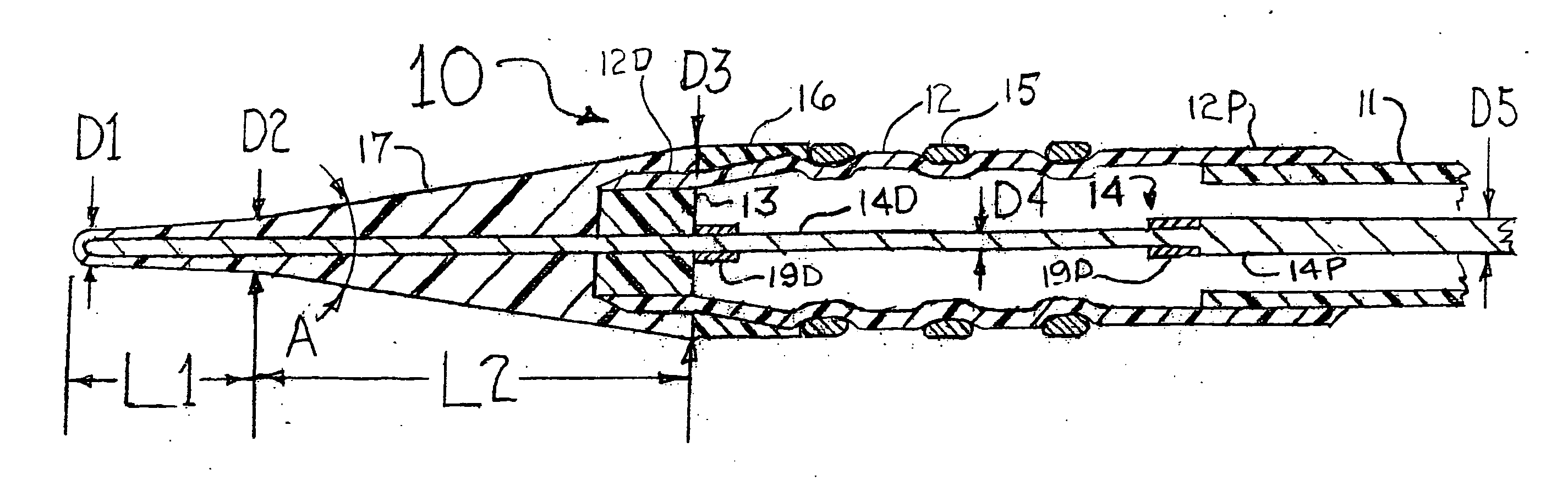
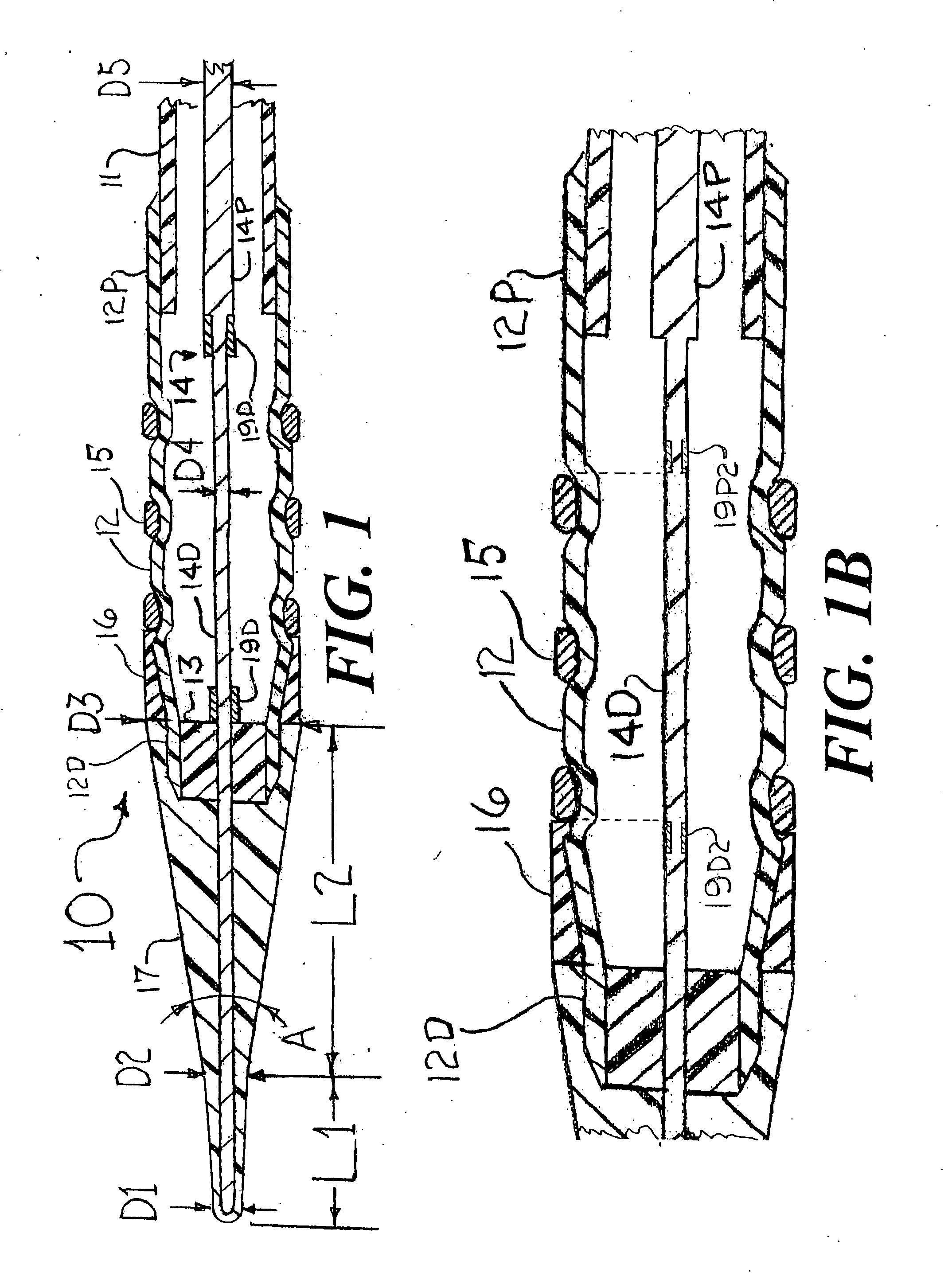
[0024]FIG. 1 is a longitudinal cross section of a distal portion of a stent delivery system 10 that has an cylindrical tube 11, a balloon 12, a balloon connector 13, a core wire 14, a stent 15, an elastomer band 16, and a front section having a small angle cone 17, a distal radiopaque marker band 19D and a proximal radiopaque marker band 19P. The cylindrical tube 11 would be formed from a thin-walled polymer that could include metal reinforcement (such as a mesh, braid, strands, etc . . . ) or, at least some of its length could be a thin-walled hypo tube or a hollow strand configuration. The balloon 12 would be a typical balloon as is well known in the art for deploying the stent 15 into an arterial stenosis. Only the outer layer of the folded balloon 12 is shown in FIG. 1. For the sake of clearly visualizing the concepts of the present invention, the scaling of FIG. 1 is such that the radial dimensions of the stent delivery system 10 are very much enlarged as compared to the scalin...


PUM


Abstract

A stent delivery system for placing a stent within a vessel of a human body. The stent delivery system includes an elongated tube that extends for most of the length of the stent delivery system and is attached to a distal end of a proximal section of an inflatable balloon. A stent is then co-axially mounted on the inflatable balloon. A front section of the stent delivery system includes a small angle cone having a lubricious outer surface. The front section is then attached to a cylindrical distal portion of the balloon and has an outside diameter at the proximal end of the small angled cone which is approximately the same diameter as the outer diameter of the stent. A core wire extends within the inflatable balloon and further into the front section of the stent delivery system.

Description

FIELD OF USE[0001]This invention is in the field of methods and devices for placing a stent within a vessel of a human body.BACKGROUND OF THE INVENTION[0002]Stents are well known devices for placement in vessels of the human body to obtain and maintain patency of that vessel. The greatest use for stents has been for placement within a stenosis in a coronary artery. When a stent is used for treating a coronary artery stenosis, it has always been necessary to first place a guidewire through the stenosis. The next step in the stenting procedure may be to pre-dilate the stenosis with a balloon angioplasty catheter that is advanced over that guidewire. The catheter may be of the over-the-wire or rapid exchange variety. The balloon angioplasty catheter is then removed and a stent delivery system which includes the stent is advanced over the guidewire, and the stent is then deployed at the site of the dilated stenosis.[0003]Recent improvements in the design of stent delivery systems have m...

Claims


Application Information

Patent Timeline
IPC IPC(8): A61F2/06
CPCA61F2002/9583A61F2/958
Inventor FISCHELL, ROBERT E.DICAPRIO, FERNANDOFISCHELL, TIM A.FISCHELL, DAVID R.FISCHELL, SCOTT J.S.
Owner FISCHELL ROBERT E
Why Eureka
Try Eureka