Mounting device for use outdoors

a mounting device and outdoor technology, applied in the direction of threaded fasteners, rod connections, instruments, etc., can solve the problems of not being able to function in a wide variety of environments, not easily customized, and known mounting devices are difficult to adjust or vary, and achieve weatherproof, durable, and convenient to adjust or vary.

Active Publication Date: 2021-07-13
WILSON CARLOS LEE
View PDF21 Cites 0 Cited by
  • Summary
  • Abstract
  • Description
  • Claims
  • Application Information

AI Technical Summary

Benefits of technology

[0006]Therefore, it is a primary object, feature, and / or advantage of the present invention to improve on or overcome the deficiencies in the art.
[0007]It is still yet a further object, feature, and / or advantage of the present invention to provide an outdoor camera mounting device that is easily adjusted or varied without requiring the use of tools.
[0008]It is still yet a further object, feature, or advantage of the present invention to provide a device that complies with any laws and regulations which apply to the intended use of the device (e.g., hunting, bird watching, wildlife viewing, etc.).
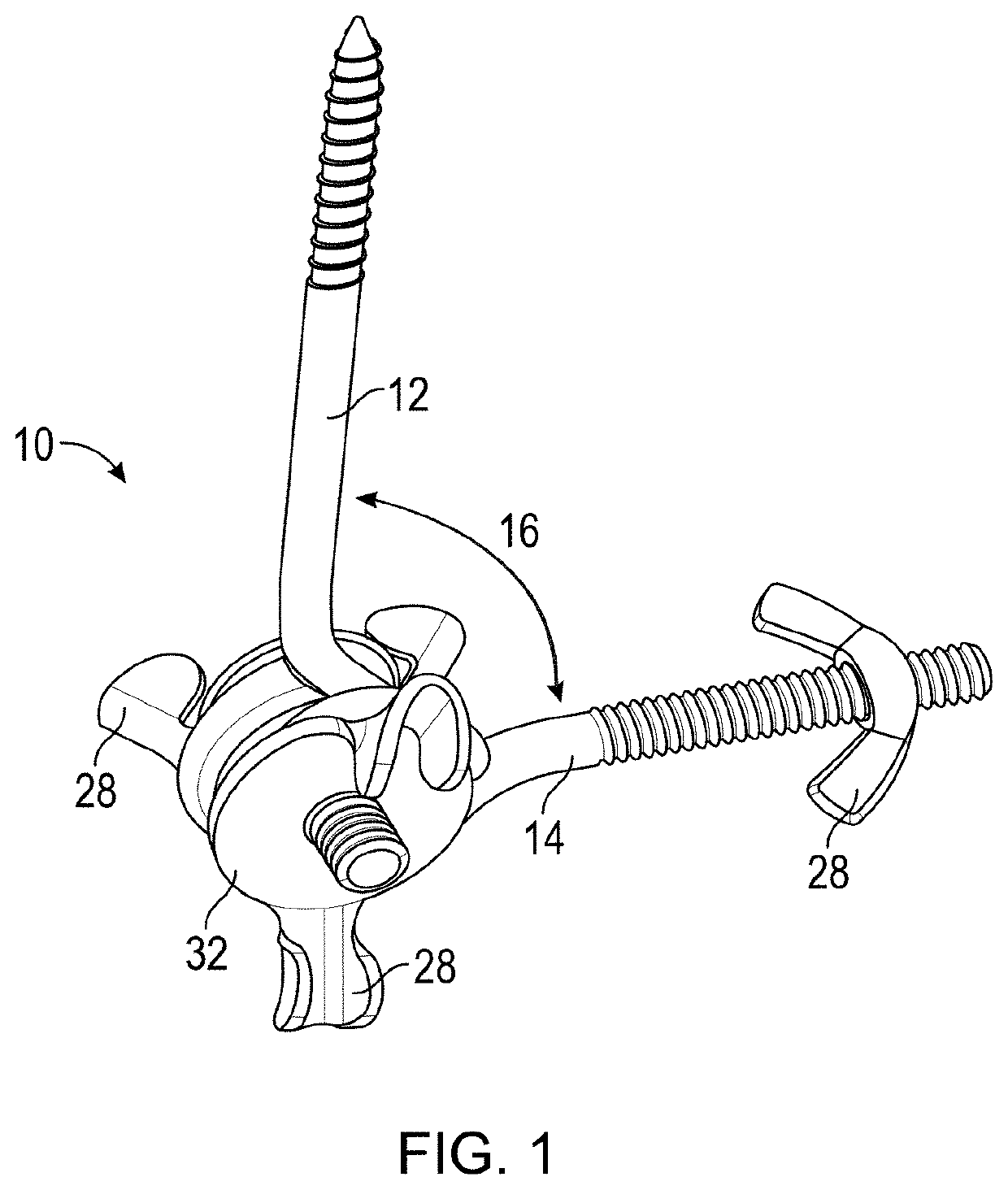
[0009]It is still yet a further object, feature, and / or advantage of the present invention to provide an outdoor mounting device that may be used with a wide variety of objects and in a wide variety of applications. For example, cameras (including security cameras), other electronic devices (e.g., tablets and phones), sensors, feed banks or bait stations, and weapon holders may all be mounted to the device. The device may be mounted to trees, step in posts, steel fence posts (also referred to as U-channel posts, T-posts, Y-posts, etc.), other similar devices, or the like.
[0010]It is still yet a further object, feature, and / or advantage of the present invention to provide a cost-effective, weatherproof, and durable outdoor camera mounting device.
[0011]It is still yet a further object, feature, and / or advantage of the present invention to provide an outdoor camera mounting device having a distinct aesthetic appearance.

Problems solved by technology

Known mounting devices are complex, bulky, expensive, time-consuming to install, not easily customized, and cannot function in a wide variety of environments.

Method used


Image

  • Mounting device for use outdoors
  • Mounting device for use outdoors
  • Mounting device for use outdoors

Examples


Embodiment Construction

Definitions—Introductory Matters

[0041]The following definitions and introductory matters are provided to facilitate an understanding of the present invention. Unless defined otherwise, all technical and scientific terms used herein have the same meaning as commonly understood by one of ordinary skill in the art to which embodiments of the present invention pertain.

[0042]The terms “a,”“an,” and “the” include both singular and plural referents.

[0043]The term “or” is synonymous with “and / or” and means any one member or combination of members of a particular list.

[0044]The terms “invention” or “present invention” as used herein are not intended to refer to any single embodiment of the particular invention but encompass all possible embodiments as described in the specification and the claims.

[0045]The term “about” as used herein refers to slight variations in numerical quantities with respect to any quantifiable variable. One of ordinary skill in the art will recognize inadvertent error...


PUM


Abstract

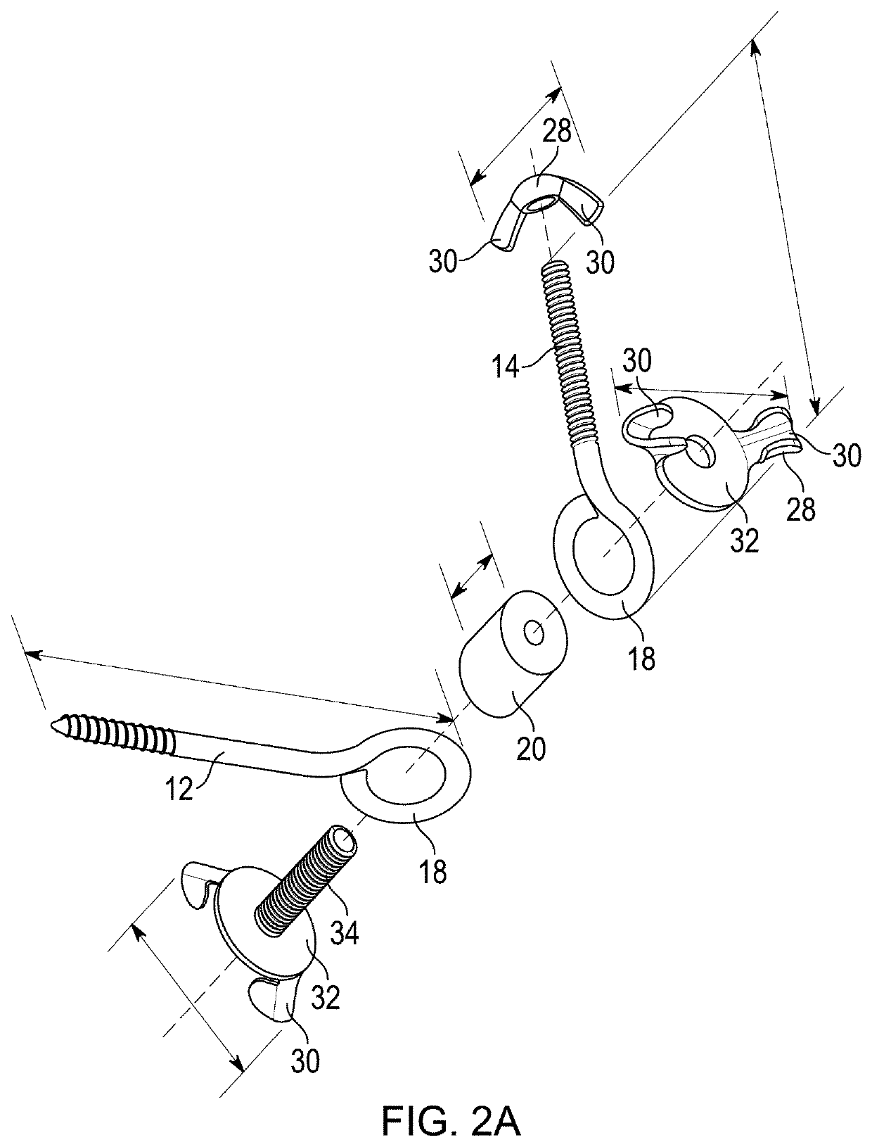
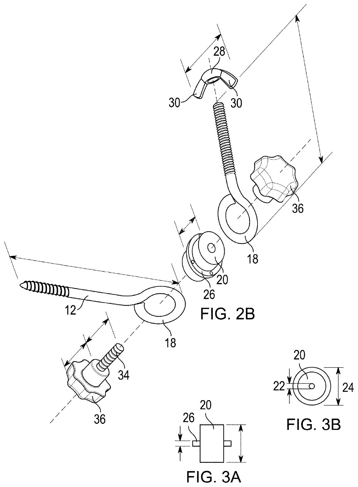
A mounting device includes a first male threaded fastening member such as a lag screw and a second male threaded fastening member such as a bolt. The male threaded fastening members are secured to one another through a joining member such as a bolt and female threaded fastening members such as wingnuts or star knobs. Tightening the female threaded fastening members fixes an angle between the male threaded fastening members without the use of tools. The first male threaded fastening member typically mounts to a tree, a post, or the ground and the second male threaded fastening member typically mounts to a camera or other electronic device. Adapters can secure the mounting device to steel fence posts or step-in posts. An internal spacing device with a flange prevents wear and tear of components of the mounting device.

Description

CROSS REFERENCE TO RELATED APPLICATIONS[0001]This application claims priority under 35 U.S.C. § 119 to provisional patent applications U.S. Ser. No. 62 / 741,651, filed Oct. 5, 2018, and U.S. Ser. No. 62 / 826,181, filed Mar. 29, 2019. The provisional patent applications are herein incorporated by reference in their entirety, including without limitation, the specification, claims, and abstract, as well as any figures, tables, appendices, or drawings thereof.FIELD OF THE INVENTION[0002]The present invention relates generally to a mounting device for use in at least the hunting, hiking, wildlife research, security, and surveillance industries. More particularly, but not exclusively, the present invention relates to a mounting device and related accessories which reduce the costs associated with and simplify the process of mounting cameras and other objects while hunting, hiking, exploring, studying wildlife, or the like.BACKGROUND OF THE INVENTION[0003]The background description provided...

Claims


Application Information

Patent Timeline
Patent Type & Authority Patents(United States)
IPC IPC(8): F16M13/02F16B37/16
CPCF16M13/022F16B37/16F16B7/044F16B7/18F16M11/10F16M11/2021F16M13/00F16M13/02F16M2200/022G03B17/561
Inventor WILSON, CARLOS LEE
Owner WILSON CARLOS LEE
Why Eureka
Try Eureka