Machine condition monitoring using pattern rules

a pattern and pattern technology, applied in the direction of mechanical roughness/irregularity measurement, testing/monitoring control system, instruments, etc., can solve the problems of complex signal pattern indicative of faults, inability to capture the rules, and time-consuming process of manual rule creation

Inactive Publication Date: 2008-10-16
SIEMENS CORP
View PDF10 Cites 10 Cited by
  • Summary
  • Abstract
  • Description
  • Claims
  • Application Information

AI Technical Summary

Benefits of technology

[0009]The present invention provides methods of machine condition monitoring and fault detection by creating pattern rules. Pattern rules are created by comparing a condition signal pattern to a plurality of known signal patterns and determining a machine condition pattern rule based at least in part on the comparison of the condition signal pattern to one of the plurality of known signal patterns. A matching score based on the comparison of the condition signal pattern to one of the plurality of known signal patterns as well as a signal pattern duration is determined. The machine condition pattern rule is then defined for nonparametric condition signal patterns as a multipartite threshold rule with a first threshold based on the determined matching score and a second threshold based on the determined signal duration. For parametric signal patterns, one or more parameters of the signal pattern are determined and the machine condition pattern rule is further defined with a third threshold based on the determined one or more parameters.

Problems solved by technology

Persistence measure-based rules may provide greater utility than simple rules and / or concatenated simple rules, but are limited in that they check the same condition at each time within the time range.
Manual rule creation is a time consuming process that requires human estimation of complex signal patterns.
Further, some signal patterns indicative of faults are highly complex and cannot be captured with the rules described above.
Accurately describing complex symptoms of faults is extremely complicated and, in many cases, intractable for a human using conventional methods of creating rules.

Method used


Image

  • Machine condition monitoring using pattern rules
  • Machine condition monitoring using pattern rules
  • Machine condition monitoring using pattern rules

Examples


Embodiment Construction

[0017]The present invention generally provides methods and apparatus for machine condition monitoring using pattern rules.

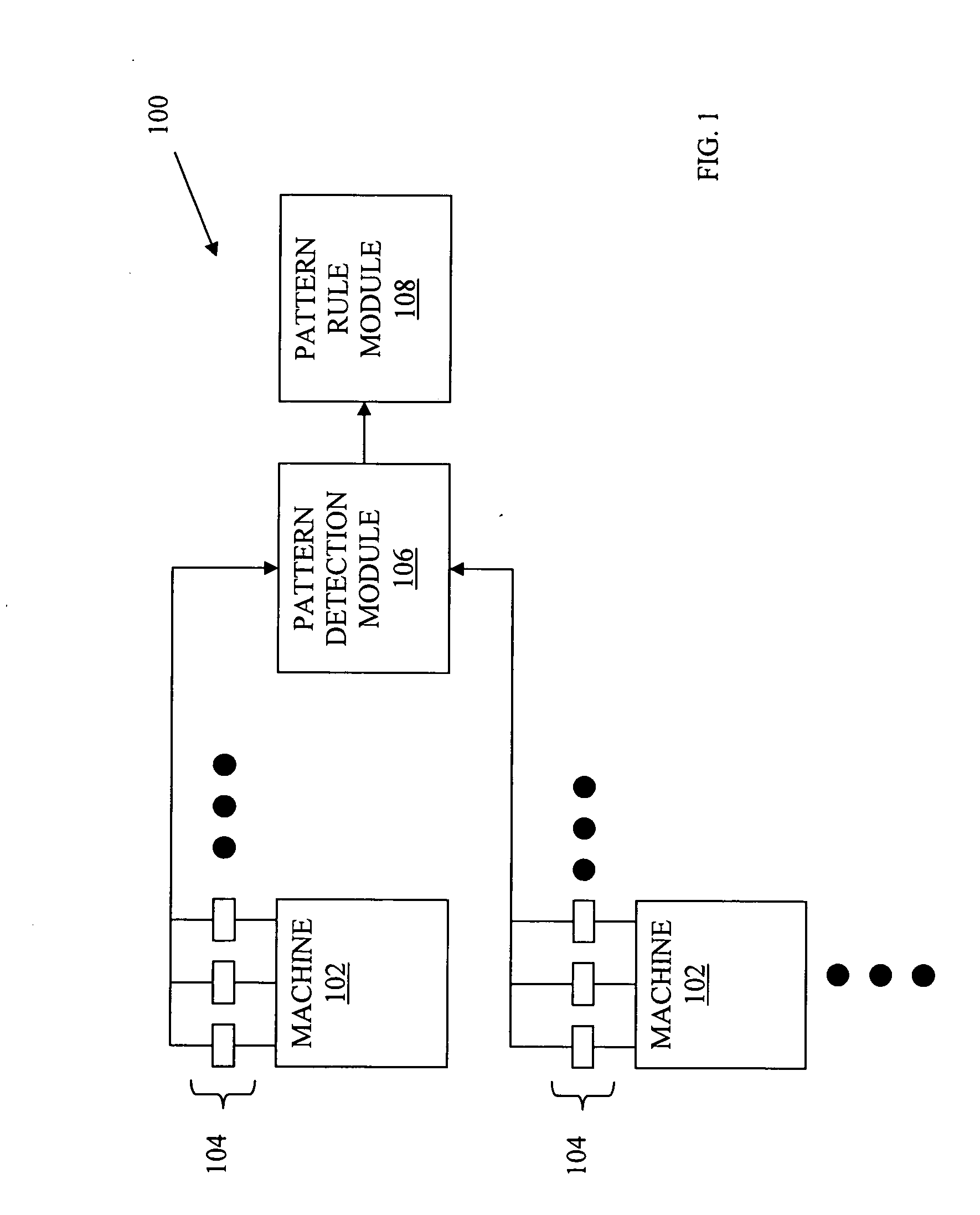
[0018]FIG. 1 depicts a machine condition monitoring system 100 according to an embodiment of the present invention. Machine condition monitoring (MCM) system 100 may be used in both the creation of pattern rules, as described below with respect to method 500 of FIG. 5, and general machine condition monitoring. MCM system 100 monitors one or more machines 102, each having one or more sensors 104. The output of sensors 104 is received at pattern detection module 106, which matches known signal patterns to patterns in the output of sensors 104. Pattern rule module 108 receives the matched patterns from pattern detection module 106 and creates pattern rules and / or detects machine faults.

[0019]Machines 102 may be any devices or systems that have one or more monitorable machine parameters, which may be monitored by sensors 104. Exemplary machines 102 include rotating a...


PUM


Abstract

Pattern rules are created by comparing a condition signal pattern to a plurality of known signal patterns and determining a machine condition pattern rule based at least in part on the comparison of the condition signal pattern to one of the plurality of known signal patterns. A matching score based on the comparison of the condition signal pattern to one of the plurality of known signal patterns as well as a signal pattern duration is determined. The machine condition pattern rule is then defined for nonparametric condition signal patterns as a multipartite threshold rule with a first threshold based on the determined matching score and a second threshold based on the determined signal duration. For parametric signal patterns, one or more parameters of the signal pattern are determined and the machine condition pattern rule is further defined with a third threshold based on the determined one or more parameters.

Description

[0001]This application claims the benefit of U.S. Provisional Application No. 60 / 911,577 filed Apr. 13, 2007, which is incorporated herein by reference.BACKGROUND OF THE INVENTION[0002]The present invention relates generally to machine condition monitoring and more particularly to determining pattern rules for use in machine condition monitoring.[0003]Machine condition monitoring (MCM) is the process of monitoring one or more parameters of machinery, such that a significant change in the machine parameter(s) is indicative of a current or developing condition (e.g., failure, fault, etc.). Such machinery includes rotating and stationary machines, such as turbines, boilers, heat exchangers, etc. Machine parameters of monitored machines may be vibrations, temperatures, friction, electrical usage, power consumption, sound, etc., which may be monitored by appropriate sensors. The output of the sensors may be in the form of and / or be aggregated into a sensor signal or a similar signal.[000...

Claims


Application Information

Patent Timeline
Patent Type & Authority Applications(United States)
IPC IPC(8): G06F19/00
CPCG05B23/0229
Inventor YUAN, CHAONEUBAUER, CLAUS
Owner SIEMENS CORP
Why Eureka
Try Eureka