
Respiratory Assistance Device

Inactive Publication Date: 2008-10-23
AIR LIQUIDE MEDICAL
View PDF25 Cites 10 Cited by
  • Summary
  • Abstract
  • Description
  • Claims
  • Application Information

AI Technical Summary

Benefits of technology

[0016]Not one of the known references of the state of the art, whether taken alone or in combination, describes, as primarily claimed by the examined invention, a centrifugal ventilation device housed in a casing and primarily composed of at least one wheel rotating at high speed, driven by a driver and equipped with a volute, where the volute is integral part of the casing so as to form an integral fixed assembly, while flexible means are intercalated between this fixed assembly and the driver equipped with the wheel it drives, these forming a dynamic assembly, to prevent the transmission of vibrations generated by the dynamic assembly towards the fixed assembly, in order to eventually reduce the sound impact of the device.
[0019]Also, the circulation channels for the gaseous flux inside the casing are lined with soundproofing material. The junction areas between the elements delimiting the internal volumes of these channels in the casing are in turn made impervious; to form an obstacle to the acoustic waves induced by the fluid circulation and to increase the soundproofing capabilities that are proper to the device proposed by the invention.
[0023]According to a first aspect of the present invention, the volute is integral to the casing so as to form an integral fixed assembly, whereas flexible means are intercalated between this fixed assembly and the driver equipped with the wheel it drives forming a dynamic assembly. These flexible means constitute the means for preventing the transmission of vibrations generated by the dynamic assembly of the device, driver and wheel in particular, towards the fixed assembly of the device, volute and casing in particular.
[0037]According to a third aspect of the present invention the material the wheel is made of is a light material such as a plastic material or a composite material of plastic matter and mineral fibers or perhaps a cellular material, in particular a rigid foam, so as to provide it with low inertia in rotation.

Problems solved by technology

A general problem to solve for these centrifugal ventilation devices lies in their soundproofing which is necessary due to the noise primarily generated by the vibrations produced by the motorization of the wheel which rotates at high speed, and by the impact of the fluid flow on the walls of the casing and in the volute.
It becomes evident that the difficulties to overcome are to prevent the transmission of these different acoustic waves so as to limit the overall sound impact of the device.

Method used


Image

  • Respiratory Assistance Device
  • Respiratory Assistance Device

Examples


Embodiment Construction

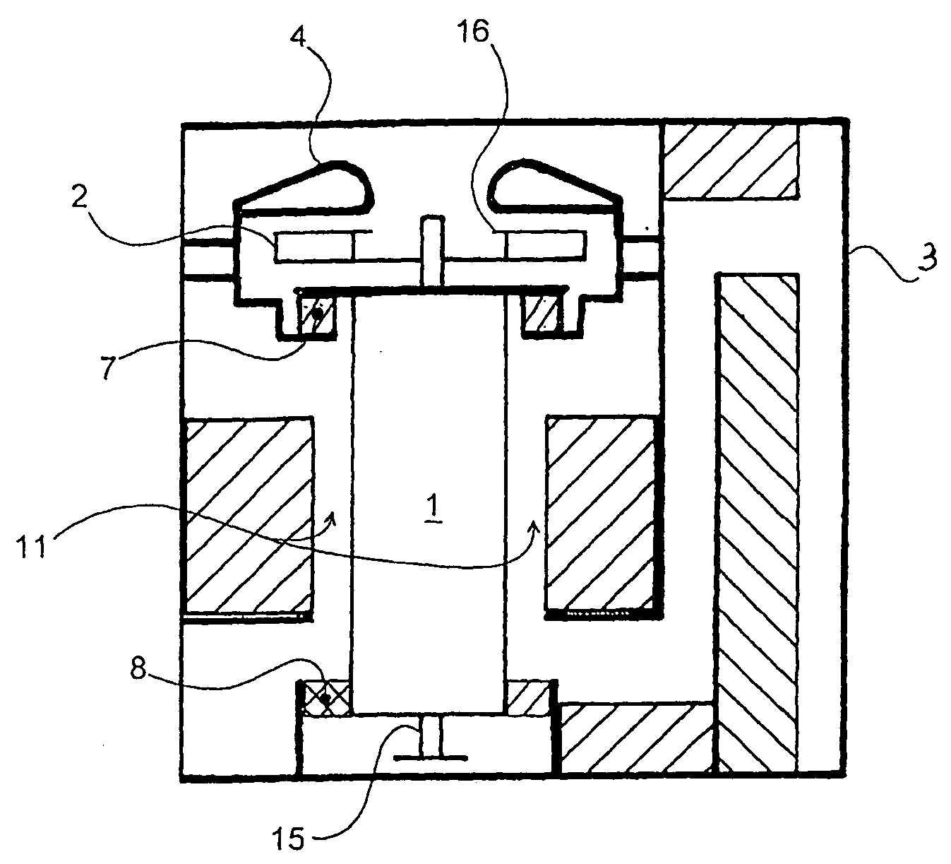
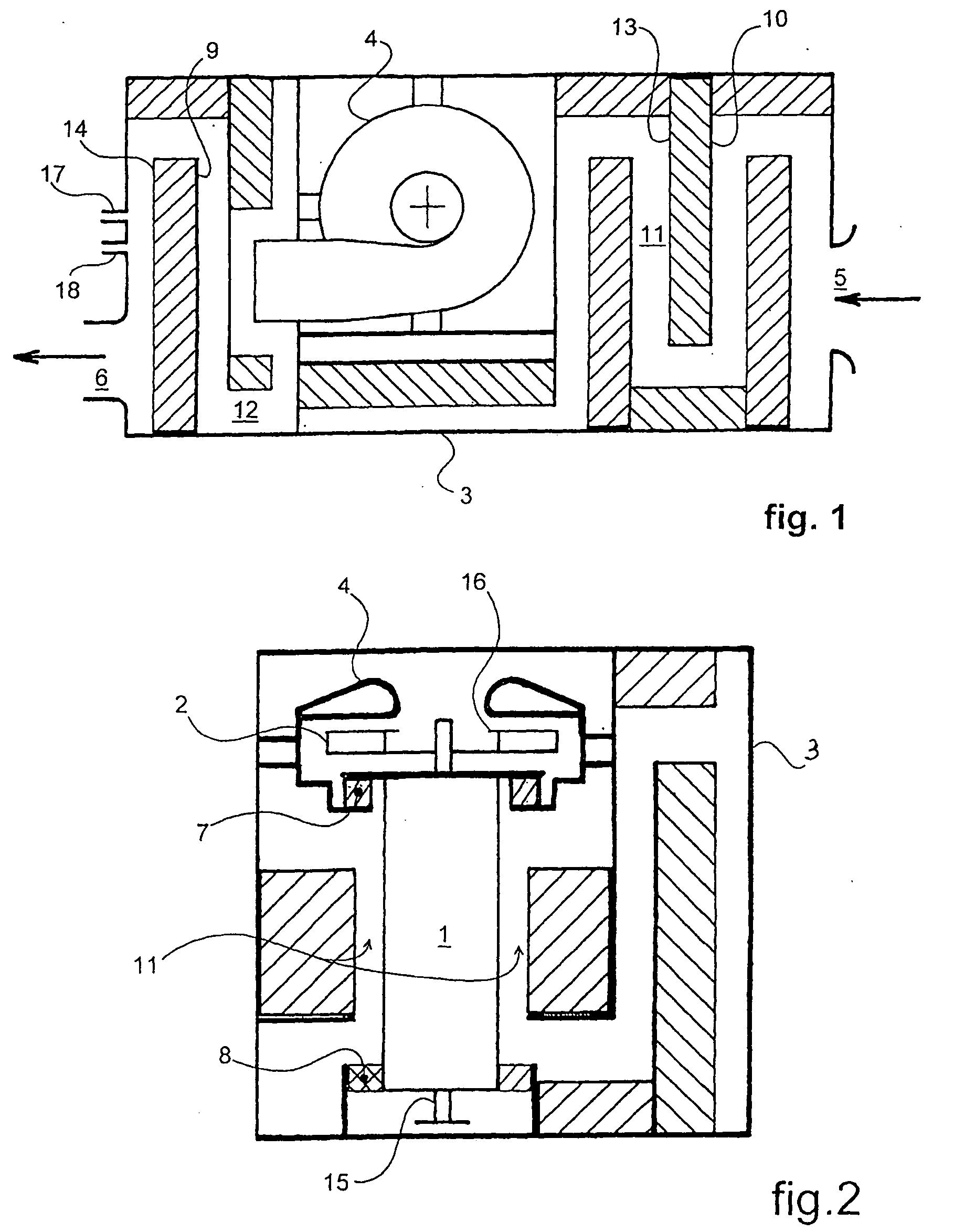
[0047]In the figures a high-speed centrifugal ventilation device is especially organized for an application to assist a patient in his respiratory function.

[0048]This device comprises in its overall form a dynamic assembly comprising a driver 1 driving a wheel 2, and a fixed assembly composed of integrated static elements, comprising a casing 3 and a volute 4 arranged around the wheel, the volute 4 being attached to the casing 3 by fitting, accessorily completed by bonding for example.

[0049]The volute 4 is intended to guide the gaseous flow drawn in by the wheel 2 from the exterior through an intake opening 5 of this gaseous flow through the casing 3, to be expelled through an output opening 6 of this gaseous flow outside of the casing 3.

[0050]Flexible elements in elastomer 7, 8 are intercalated between the fixed assembly 3, 4 and the dynamic elements 1, 2 of the device. More precisely these elements comprise a first flexible element intercalated between the volute 4 and the driver ...


PUM


Abstract

The high-speed centrifugal ventilation device for assisting a patient respiratory function includes a centrifugal fan which is arranged in a casing box and essentially has a wheel actuated by a driver. The wheel is provided with a volute connected to the casing box in such a way that an integral fixed assembly is formed. An elastic device is interposed between the fixed assembly and the driver provided with the wheel which is driven thereby. A dynamic assembly is formed for avoiding transmission of vibrations generated by the wheel and the driver towards the fixed assembly.

Description

RELATED U.S. APPLICATIONS[0001]Not applicable.STATEMENT REGARDING FEDERALLY SPONSORED RESEARCH OR DEVELOPMENT[0002]Not applicable.REFERENCE TO MICROFICHE APPENDIX[0003]Not applicable.FIELD OF THE INVENTION[0004]The present invention is in the area of devices acting on the respiratory system of patients, actuating a pumping apparatus for a gaseous flux. More specifically its subject is a high-speed centrifugal ventilation device for assisting a patient's respiratory function.BACKGROUND OF THE INVENTION[0005]As is well known, there are centrifugal ventilation devices for assisting a patient's respiratory function which comprise in general a centrifugal ventilator housed inside a casing and essentially consists of at least of a wheel rotating at high speed, actuated by a driving element and provided with a volute. The gaseous flux is drawn in through an inlet opening in the casing, to be expelled from this casing through an evacuation opening, after its passage into the ventilator comp...

Claims


Application Information

Patent Timeline
Patent Type & Authority Applications(United States)
IPC IPC(8): A61M16/00F04D29/04F04D29/66
CPCA61M16/0057A61M16/0066A61M2205/42F04D29/051F04D29/668
Inventor GRASMUCK, GILBERT
Owner AIR LIQUIDE MEDICAL
Learn More