Apparatus and methods for ferromagnetic wall inspection of tubulars

a technology of ferromagnetic wall and apparatus, which is applied in the field of magnetic inspection, can solve the problems of inability to accurately measure an anomaly in the magnetic field, disturb the uniformity of the magnetic field in the wall, and many methods in the field

Inactive Publication Date: 2008-10-23
SCAN SYST
View PDF14 Cites 8 Cited by
  • Summary
  • Abstract
  • Description
  • Claims
  • Application Information

AI Technical Summary

Benefits of technology

[0009]In accordance with the present invention, apparatus and methods are described that reduce or overcome problems in previously known apparatus and methods for magnetic wall inspection of tubulars.

Problems solved by technology

The presence of structural flaws or anomalies in the wall of the tubular member, such as surface nicks or pits, cracks, voids, or various crystalline discontinuities, disturbs the uniformity of a magnetic field in the wall of the tubular member.
However, the method has been unacceptable for many in the field due to “blooming” of the magnetic field lines of flux as the inspection nears an end area 10 of a tubular is approached.
In this 4 feet (122 cm) of the tubular it is currently impossible to accurately measure an anomaly in the magnetic field indicative of a defect (flaw, reduced wall thickness, and the like) in the tubular.
All of this is expensive and time consuming.

Method used


Image

  • Apparatus and methods for ferromagnetic wall inspection of tubulars
  • Apparatus and methods for ferromagnetic wall inspection of tubulars
  • Apparatus and methods for ferromagnetic wall inspection of tubulars

Examples


embodiment 50

[0035]As indicated in FIG. 5, lines of magnetic flux 6 from main coil 4 generally find the tubular member 2 during magnetic wall inspection, however, some of the magnetic lines of flux, such as the outer-most magnetic lines, may stray away from the tubular. This is illustrated in FIG. 5 near an end 10 of tubular 2, but this phenomenon may also occur remote from the ends of tubulars, so apparatus and methods of the invention are not limited to inspection of ends of tubulars. In embodiment 50 of FIG. 5, focusing coil 5 supplies auxiliary lines of magnetic flux 6a, and since lines of magnetic flux do not cross, auxiliary lines of magnetic flux 6a serve to push, steer, focus, direct or re-direct magnetic flux lines 6 in the areas 12, 14, so that they become more parallel to the tubular being inspected, and be useful in detecting flaws in the tubular.

[0036]FIG. 6 illustrates an apparatus embodiment 60 similar to embodiment 50 of FIG. 5, the only difference being the inclusion of two focu...
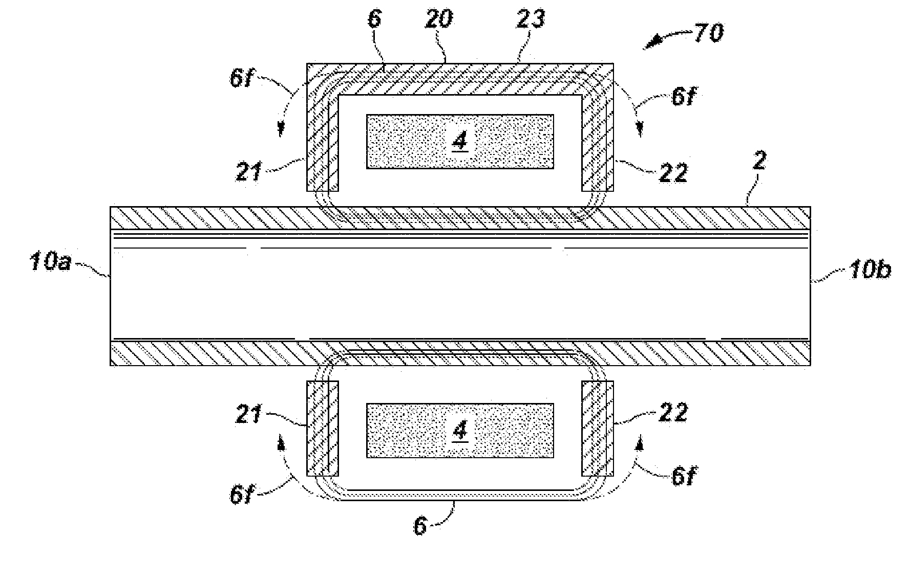
embodiment 70

[0037]FIG. 7 illustrates an embodiment 70 within the invention wherein the focusing member is a yoke 20 having two portions 21, 22, generally perpendicular to tubular member 2, and a connecting portion 23 generally parallel to the longitudinal axis of the tubular 2. Yoke portions 21, 22 serve to focus, direct, re-direct or steer magnetic lines of flux 6f so that they are more parallel to tubular 2.

embodiment 80

[0038]FIG. 8 illustrates an embodiment 80 within the invention which is essentially a combination of embodiments 60 and 70. Magnetic lines of flux 6g that otherwise would not be as parallel to tubular 2 are directed by a combination of “pushing” by fields 6a, 6b from focusing coils 5a, 5b, respectively, and “pulling” by yoke portions 21, 22. With this embodiment, the entire tubular, including up to about 12-18 inches (30-45 cm) from each end 10a, 10b of the tubular 2 may be inspected using magnetic wall inspection. The curve A in FIG. 9 exemplifies the result of using a yoke and focusing coils in conjunction with a main magnetic coil. Curve A normalizes, or becomes stable, much more quickly than Curve B which illustrates a result when not using a yoke and focusing coils. It is theorized that by employing a different design of yoke (for example a thicker yoke or longer yoke) it may be possible to eliminate the need for focusing coils, and inspect even closer to the ends of the tubula...


PUM

PropertyMeasurementUnit
thicknessaaaaaaaaaa
resistanceaaaaaaaaaa
thicknessaaaaaaaaaa

Abstract

Apparatus and methods for magnetic wall inspecting materials such as cylindrical and tubular members are disclosed. One apparatus includes a main magnetic coil producing lines of magnetic flux able to traverse a section of a tubular member in a direction generally parallel to a longitudinal axis of the tubular member; and one or more magnetic focusing members positioned along the tubular and able to redirect certain flux lines so that they are more parallel to the tubular. This abstract allows a searcher or other reader to quickly ascertain the subject matter of the disclosure. It will not be used to interpret or limit the scope or meaning of the claims. 37 CFR 1.72(b).

Description

FIELD OF THE INVENTION[0001]1. Field of Invention[0002]The present invention relates generally to the field of magnetic inspection, and more specifically to apparatus and methods of using same for magnetic wall inspection of materials such as cylindrical and tubular members. The invention was the result of a written joint research agreement (as defined in 35 USC 103(c)) entered into between the University of Houston and Scan Systems Corporation for the performance of experimental, developmental, and / or research work in the field of the claimed inventions.[0003]2. Related Art[0004]Inspection of metal pipe or solid tubular members by magnetic means conventionally involves magnetizing the member to create a magnetic field which extends circumferentially and is characterized by lines of magnetic flux which extend either axially of the tubular member or generally perpendicular to its axis, dependent on the manner by which magnetism is induced. In many of the present systems, current flow...

Claims


Application Information

Patent Timeline
Patent Type & Authority Applications(United States)
IPC IPC(8): G01N27/82
CPCG01N27/87
Inventor PUTMAN, PHILIP T.WALTERS, WILLIAM T.USELTON, DANNY J.
Owner SCAN SYST
Why Eureka
Try Eureka