Digital phase modulator and corresponding method

a digital phase modulator and digital phase technology, applied in the field of digital phase modulator and corresponding method, can solve the problems of affecting the performance of the signal processing system, the inability to integrate the hardware into the digital electronic module such as asics, fpgas, cplds and suchlike, and the hardware is comparatively complicated in hardware, so as to achieve stable phase jump, minimal installation space, and the effect of facilitating transmission

Active Publication Date: 2008-10-23
SIVANTOS PTE LTD
View PDF5 Cites 0 Cited by
  • Summary
  • Abstract
  • Description
  • Claims
  • Application Information

AI Technical Summary

Benefits of technology

[0015]It is also advantageous if the counter is clocked with a quartz oscillator. Very stable phase jumps can thus be achieved.
[0016]According to a further advantageous embodiment, the counter, the comparator and a transmission stage are integrated in a common logic module. In this way, a phase modulator with minimal installation space and transmission functionality can be realized very easily. Only the external antenna need still be connected.
[0017]The use of the inventive digital phase modulator and / or the said inventive method in a hearing device is particularly advantageous. It is possible in this case to profit particularly from the minimal installation size of this digital phase modulator as well as from the associated reduced interferences. Furthermore, it can also be used with associated remote controllers.

Problems solved by technology

The individual methods are mostly comparatively complicated to realize in the hardware and an integration of this hardware into digital electronic modules such as ASICs, FPGAs, CPLDs and suchlike is barely possible.
The results are correspondingly high interferences.
As hearing devices are however generally designed to be structurally very small, the lines lie correspondingly close to one another such that with conventional phase modulation methods, more interferences result.

Method used


Image

  • Digital phase modulator and corresponding method
  • Digital phase modulator and corresponding method

Examples


Embodiment Construction

[0022]The exemplary embodiment illustrated in more detail below represents a preferred embodiment of the present invention.

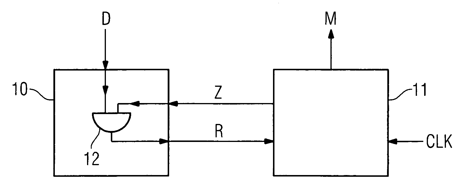
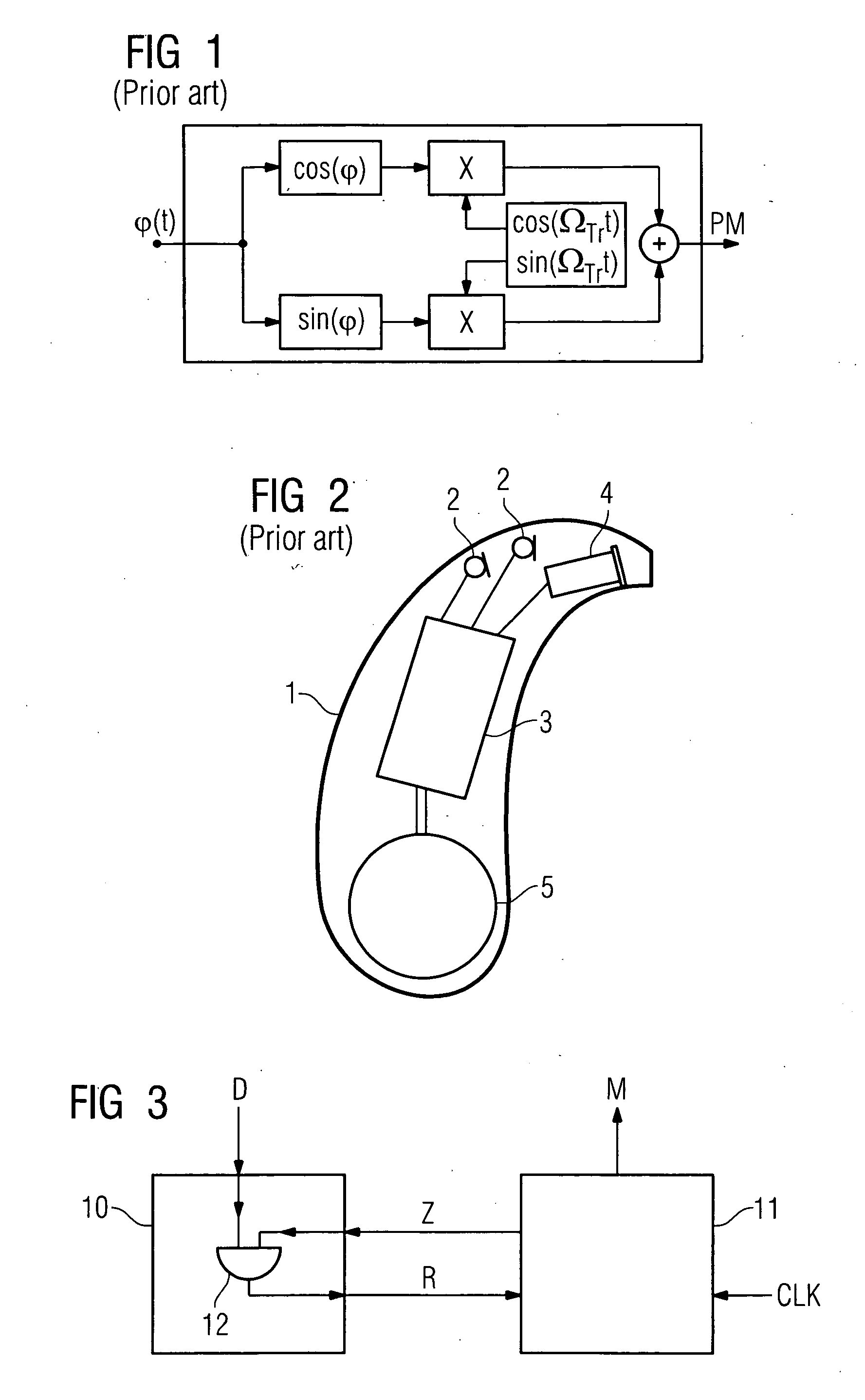
[0023]The exemplary embodiment of an inventive digital phase modulator reproduced in FIG. 3 only consists of two essential components, a comparator 10 and a counter 11. The comparator 10 receives the digital data D, which is to be modulated in its phase. The comparator 10 also receives a counter state Z from the counter 11. The data D and the counter state Z, symbolized by an AND element, are compared with one another in the comparator 10. The output signal of the AND element 12 is used as a reset signal R for synchronously resetting the counter 11 and is accordingly fed hereto.

[0024]The counter 11 is itself fed by a clock CLK, which has a much higher frequency than the input signal D. The output signal M of the counter 11 is the correspondingly phase-modulated input signal.

[0025]For digital data transmission, it can also be seen from FIG. 3 that in the case of ...


PUM


Abstract

A simple, interference-free digital phase modulator is to be provided. To this end, the phase modulator is provided with a counter for outputting a counter signal on the basis of a predetermined clock signal and a comparator, which receives a current counter state from the counter, in order to record a digital input signal. The comparator compares the input signal with the current counter state on the basis of a predetermined allocation table and resets the counter, if the input signal corresponds to a counter state assigned via the allocation table. A predetermined signal value of the output counter signal is herewith phase-modulated as a function of the input signal. As only one phase position is generated with the circuit at any point in time, interferences, which are produced by the digital phase modulator itself, are significantly less.

Description

CROSS REFERENCE TO RELATED APPLICATIONS[0001]This application claims priority of German application No. 10 2007 018 087.1 DC filed Apr. 17, 2007, which is incorporated by reference herein in its entirety.FIELD OF INVENTION[0002]The present invention relates to a digital phase modulator and a corresponding method for generating a phase-modulated signal. In particular, the digital phase modulator and the method can be used for a hearing device.BACKGROUND OF INVENTION[0003]In order to transmit data by radio, modulations, for instance the amplitude modulation, the frequency modulation or the phase modulation, of a carrier signal are generally carried out. A suitable method is to be selected for each modulation. The individual methods are mostly comparatively complicated to realize in the hardware and an integration of this hardware into digital electronic modules such as ASICs, FPGAs, CPLDs and suchlike is barely possible.[0004]Previous modulators generally operate according to FIG. 1 w...

Claims


Application Information

Patent Timeline
Patent Type & Authority Applications(United States)
IPC IPC(8): H04L27/20
CPCH04R2225/51H04L27/2092
Inventor REITHINGER, JURGEN
Owner SIVANTOS PTE LTD
Why Eureka
Try Eureka