Electrical contact device for a fuel cell stack

a technology of electrical contact device and fuel cell stack, which is applied in the direction of fuel cell details, electric generators, fuel cells, etc., can solve the problems of reducing the efficiency of the fuel cell stack, water from the operating media or exhaust gases condensing out on the end plates, and causing danger, so as to achieve the minimum installation space requirement of the electrical contact device, increase resistance, and increase heat accumulation

Active Publication Date: 2020-09-29
AUDI AG
View PDF5 Cites 0 Cited by
  • Summary
  • Abstract
  • Description
  • Claims
  • Application Information

AI Technical Summary

Benefits of technology

[0022]The contact regions of the electrical contact device thereby serve both for the diversion of charges from the fuel cell stack and as a resistance heating element for the production of heat. The installation space requirement of the electrical contact device is thus minimal. The switching element makes it possible to disconnect individual contact regions from the load current circuit, and thus to adjust the contact device resistance. A variable heating of the stack end plates is consequently enabled. For example, during a cold weather start, a high resistance of the contact device may be set at first in order to heat the stack end plates. Then the resistance is reduced, and the efficiency of the stack thus increases.
[0025]The direct connection between at least one contact region and the load current circuit via the first contact structure may be disconnected by operation of the at least one switching element. Then the current flows from this contact region across at least one second contact structure, an adjacent contact region, and finally across the first contact structure connected to this contact region, into the load current circuit. Because of the differing electrical resistances of the first and second contact structures, the operation of the at least one switching element substantially modifies the overall resistance of the contact device. In particular when the second contact elements have an increased resistance, there is a substantially higher overall resistance of the contact device in the series circuit of the contact regions.
[0028]In an especially preferred embodiment, the contact device has a plurality of first contact regions and a plurality of second contact regions, and at least one switching element arranged between the plurality of second contact regions and the external load current circuit. The first contact regions in this arrangement preferably have a different electrical resistance than the second contact regions. For example, a plurality of first contact regions may be electrically conductively connected to a load current circuit via a first bundle of first contact structures, and a plurality of second contact regions may be connected to the load current circuit via a second bundle of first contact structures. If at least one switching element is arranged in the first bundle of first contact structures, the plurality of first contact regions is disconnected from the load current circuit by operation of the switching element. In this way, the overall resistance of the contact device, and thus the Joule heat produced by it at constant voltage, is substantially increased. This increase may be strengthened or reduced by adjustment of the resistances of the first contact regions relative to the second contact regions. According to this embodiment, the first and second contact regions are especially preferably each designed in the shape of finger structures that engage with one another. A homogeneous current extraction via the contact device is thus ensured regardless of the state of the switching element.

Problems solved by technology

The danger therefore exists that water from the operating media or exhaust gases condenses out on the end plates.
This condensation water can block flow channels, for example in the flow fields of the bipolar plate, and thus reduce the efficiency of the fuel cell stack.

Method used


Image

  • Electrical contact device for a fuel cell stack
  • Electrical contact device for a fuel cell stack
  • Electrical contact device for a fuel cell stack

Examples


first embodiment

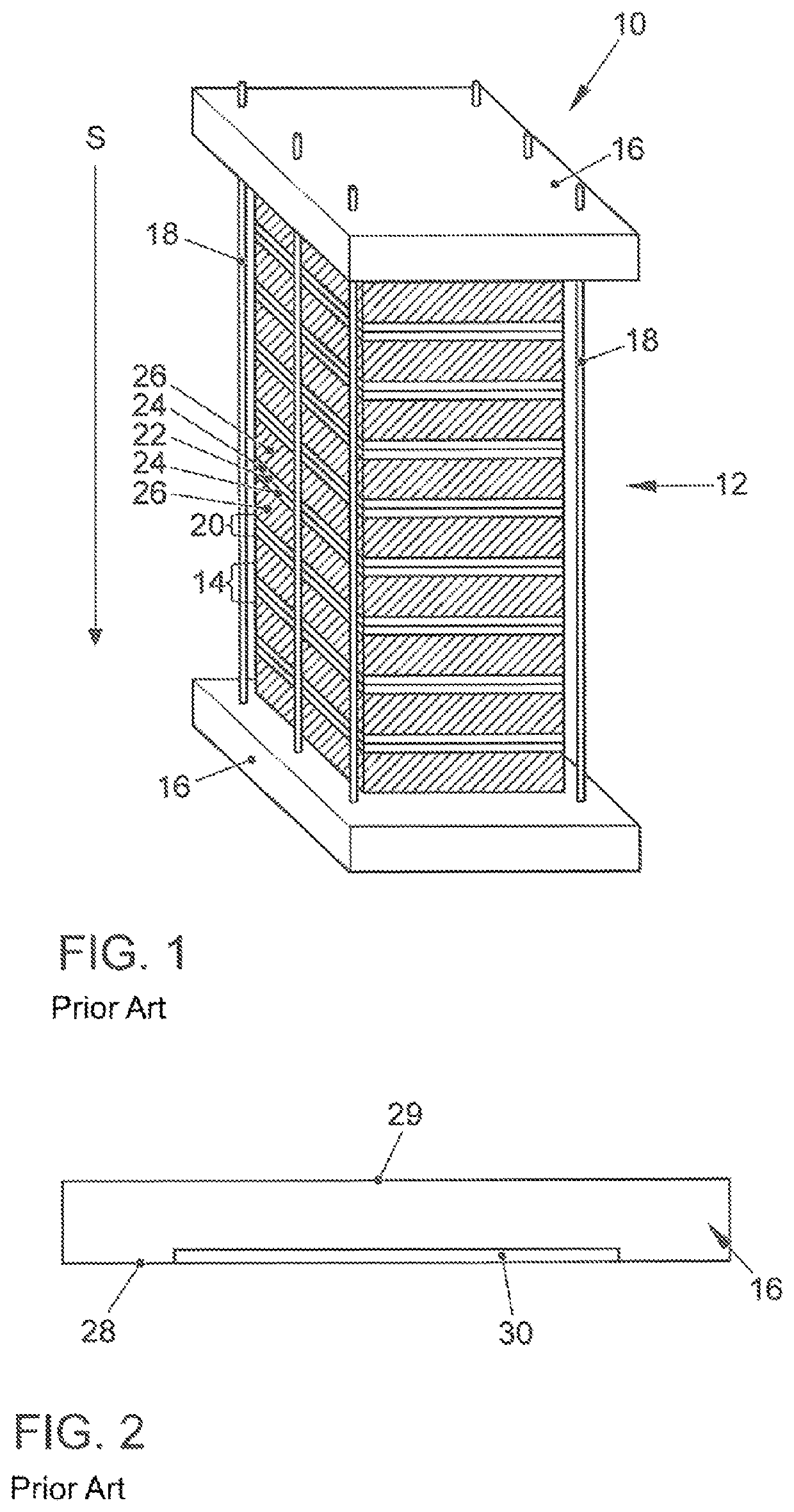
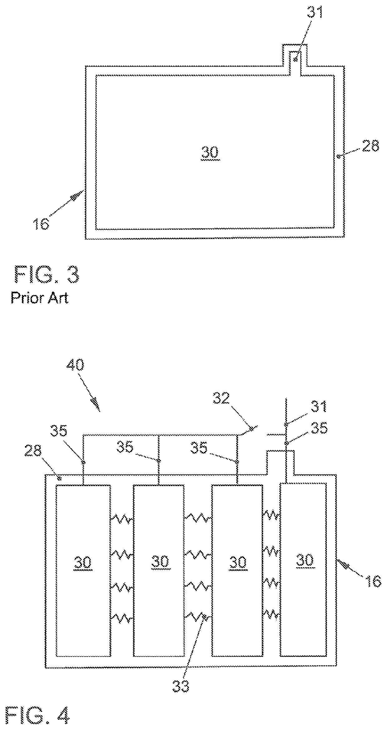
[0043]FIG. 4 shows an electrical contact device 40 according to a Contact device 40 may be arranged in one or a plurality of recesses of first main surface 28 of an end plate 16, as depicted in FIG. 2. Alternatively, contact device 40 may be arranged above the first main surface 28 of end plate 16, and an elastic insulating film may be arranged between contact device 40 and end plate 16.

[0044]The contact device according to the first embodiment has four contact regions 30 which are formed by thin copper layers. The copper layers 30 were preferably electrostatically deposited on end plate 16 or on an insulation plate arranged between end plate 16 and contact structure 40. Each of the contact regions 30 is connected via a first contact structure 35 to an external load current circuit 31, of which only a section is depicted. A contact region 30 arranged toward the outside is directly connected to load current circuit 31 via a first contact structure 35. The first contact structures 35...

second embodiment

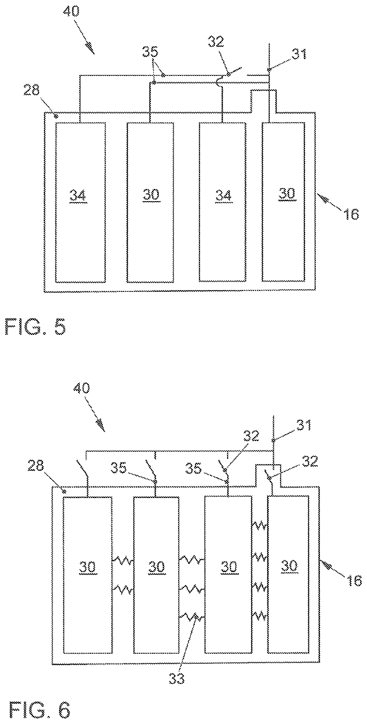
[0048]In contrast to FIG. 4, an electrical contact device 40 according to the present disclosure which is shown in FIG. 5 has a plurality of first contact regions 30 and a plurality of second contact regions 34. The first and second contact regions 30, 34 engage with one another in the manner of fingers. First contact structures 35 connected to first contact regions 30 are bundled, just as are first contact structures 35 connected to second contact regions 34. Bundled first contact regions 30 are simply connected to load current circuit 31, whereas a switching element 32 is arranged between bundled second contact regions 34 and load current circuit 31. In contrast to the embodiment shown in FIG. 4, the contact device 40 shown in FIG. 5 has no second contact structures 33.

[0049]In a first working position of switching element 32, it produces an electrically conductive connection between the bundle of first contact structures 35, which are connected to second contact regions 34, and l...

third embodiment

[0050]an electrical contact device 40 according to the present disclosure as shown in FIG. 6 again has four uniform contact regions 30. Each contact region 30 is connected via a first contact structure 35 to an external load current circuit 31, wherein a switching element 32 is arranged in each first contact structure 35 between each contact region 30 and the load current circuit 31. Therefore, a direct connection can be either disconnected or established between each contact region 30 and load current circuit 31 by operation of the respectively associated switching element 32. The number of contact regions 30 that are connected in parallel with respect to the load current circuit is therefore variable.

[0051]Second contact structures 33 each connect two adjacent contact regions 30 to each other in an electrically conductive manner. In this arrangement, the electrical resistance of second contact structures 33 varies within contact device 40. In FIG. 6, this is depicted by variation ...


PUM

PropertyMeasurementUnit
electrical currentaaaaaaaaaa
electrically conductiveaaaaaaaaaa
electrical resistanceaaaaaaaaaa

Abstract

An electrical contact device for the diversion of electrical current from a fuel cell stack can have a plurality of electrically conductive contact regions which are delineated from each other. A plurality of electrically conductive first contact structures connects each, or a plurality of, the contact region(s) to an external load current circuit. Via at least one switching element arranged in a first contact structure, an electrically conductive connection may be disconnected by the first contact structure, in particular between at least one contact region and a load current circuit. In this way it is possible to adjust the overall resistance of the contact structure, and thus the Joule heat produced in the contact regions. Second contact structures that are arranged between the contact regions enable a further increased variability of the overall electrical resistance of the contact device.

Description

BACKGROUNDTechnical Field[0001]The present disclosure relates to an electrical contact device for a fuel cell stack, and to a fuel cell stack including such an electrical contact device.Description of the Related Art[0002]Fuel cells use the chemical conversion of a fuel with oxygen to water to generate electrical energy. For this reason, fuel cells have as a core component a membrane electrode assembly (MEA) having a membrane electrode unit. The latter is formed by a proton-conducting membrane, on both sides of which are arranged catalytic electrodes. In this arrangement, the membrane separates the anode chamber associated with the anode and the cathode chamber associated with the cathode from each other in a gas-tight manner and insulates them electrically. It is also possible to arrange gas diffusion layers on the sides of the electrodes that do not face toward the membrane.[0003]During operation of the fuel cell, a fuel containing hydrogen is supplied to the anode, at which an el...

Claims


Application Information

Patent Timeline
Patent Type & Authority Patents(United States)
IPC IPC(8): H01M8/04858H01M8/241H01M8/24H01M8/04007H01M8/0228H01M8/0202H01M8/0267H01M8/1018
CPCH01M8/0267H01M8/24H01M8/241H01M8/0269H01M8/0228H01M8/04037H01M8/04895H01M2008/1095H01M8/0258H01M8/2465H01M8/247H01M8/249Y02E60/50
Inventor STEWART, IANMOSS, BEVAN HOSKYN
Owner AUDI AG
Why Eureka
Try Eureka