GPS-Based Location and Messaging System and Method

a location and messaging system technology, applied in static indicating devices, instruments, data processing applications, etc., can solve the problems of user inability to locate the destination, information gives a very incomplete understanding of visually identifying a destination, and can be confusing between different perspectives, so as to achieve convenient display

Active Publication Date: 2008-10-23
SPATIAL REALITY LLC
View PDF45 Cites 67 Cited by
  • Summary
  • Abstract
  • Description
  • Claims
  • Application Information

AI Technical Summary

Benefits of technology

[0011]The present invention contemplates a GPS system that provides target area information relevant to the viewer's selected perspective or location or is selectable to view the target area to another location or target. Preferably, the object is a target location, such as a destination location and the target is conveyed in the context of its background environment, such as a row of buildings on a city street. The user preferably has a portable viewing device that accepts the user's GPS derived position and selectively displays a view of the target from the user's perspective or location or selectively from another location. Preferably, the user's portable viewing device includes an orientation indicator so that the user has feedback indicating the device is pointed towards the desired target. That is, the user can selectively view and identify a target from different locations, views, and magnification and the user can tell if the viewing device is oriented correctly. Even remote users can use a device with a network information feed to identify a target. In a preferred form, a geo-referenced billboard is included on or near the target and conveys information to the user. For example, messages such as advertisements or the name of the target can be conveniently displayed on the billboard.

Problems solved by technology

For example, at a NASCAR race, the TV or radio viewing location limits his view of the race and is not his own unique perspective.
Such divergent perspectives—announcer versus personal—can be confusing.
In navigation and locator GPS-based systems, what is lacking is an integrated GPS system for an individual user to gain situational awareness and to easily identify destinations or other areas of interest.
That is, while a user might possess a GPS-enabled cell phone that transmits his position and gives text based directions to a destination, this information gives a very incomplete understanding to visually identify a destination.
A particular problem in the area of personal navigation is identifying a place of interest in a confusing environment, such as a crowded street.
For example, a cell phone having a GPS might be enabled to identify that a destination is near, but the user cannot locate the destination because of the clutter or environment, e.g. a crowded street or neighborhood or obstructions to the user's line of sight.
Users also have difficulty relating how a small mark identifying a place on a map correlates to their position or their view of the environment.

Method used


Image

  • GPS-Based Location and Messaging System and Method
  • GPS-Based Location and Messaging System and Method
  • GPS-Based Location and Messaging System and Method

Examples


Embodiment Construction

Sport System

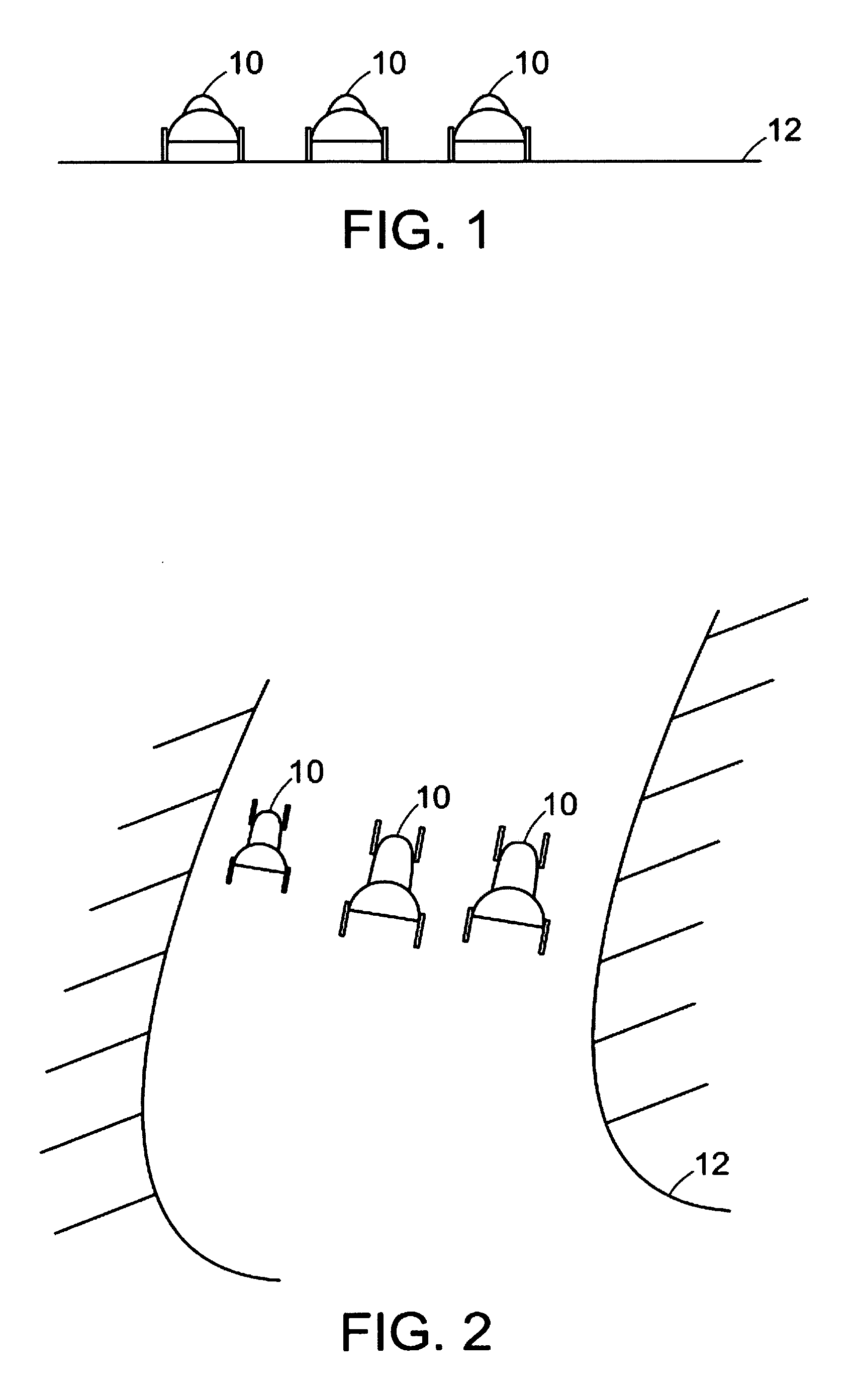
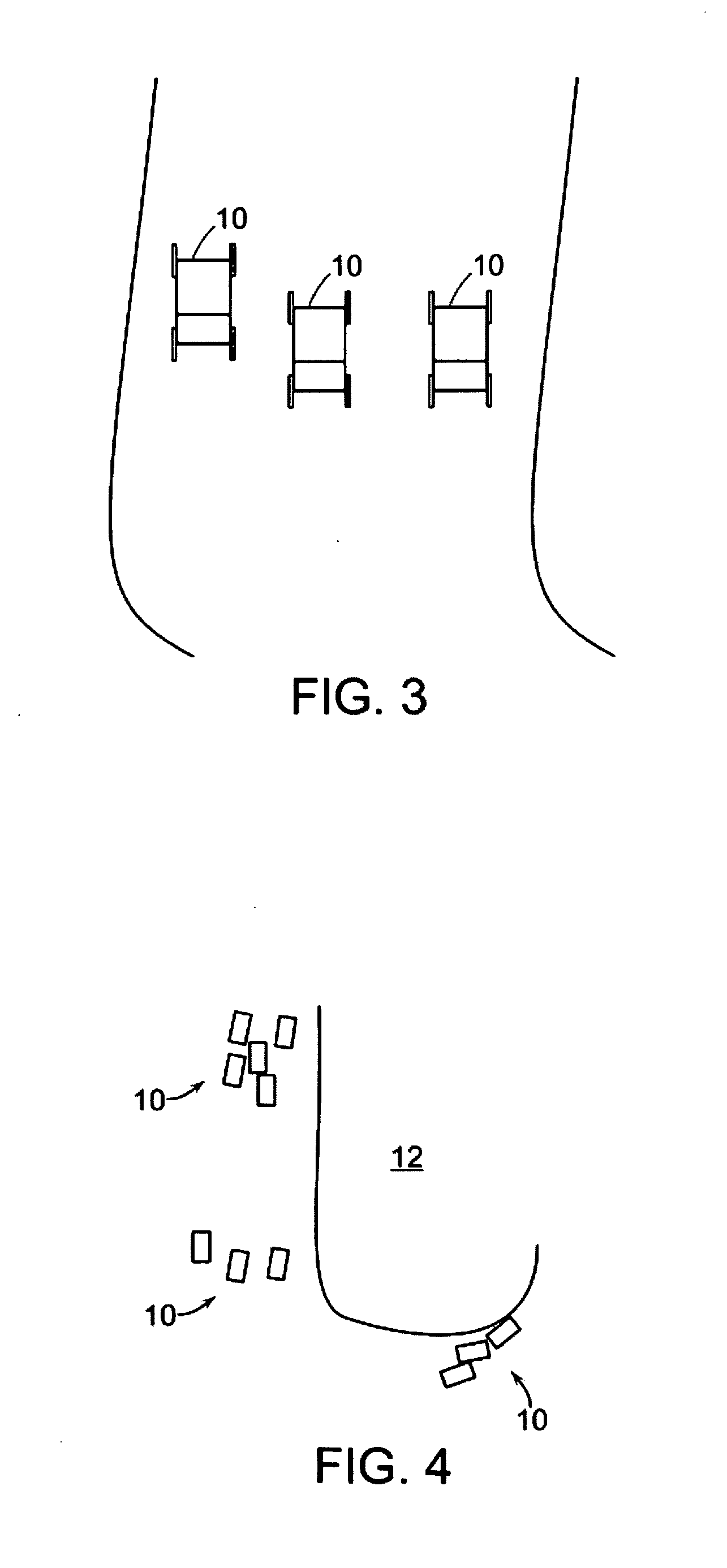
[0031]Turning to the drawings, cars 10 traverse a track 12. In FIG. 1, the spectator has selected a position at the 3rd turn of an oval track and FIG. 1 is a rendering similar to the spectator's selected view. In FIG. 2, the spectator has tilted upwardly his view so that the spectator has an oblique angle view of the cars 10 of FIG. 1. FIG. 3 is the same depiction of the cars on the track, but the view is further tilted upward to a direct, overhead view of the track 12.

[0032]FIG. 4 is of a view of the same cars 10 on the track 12 at the same moment in time as FIGS. 1-3, but the view is “zoomed” outwardly changing the scale and allowing the spectator to see more of the cars 10 on the track 12. FIG. 5 is similar in scale to FIG. 4, but the perspective has been changed to the finish line. While the display of the track 12 in FIGS. 1-4 is of an actual race, at time trials the spectator could alternatively obtain from a server a “SimulCam” using technology such as available f...


PUM


Abstract

A system and method for viewing a target in a background from a user's perspective. In one form, the views are selectable by the user on, for example, a GPS equipped cell phone, to include a view from the participant's position, zoom, pan, and tilt views, or views from another geographic location, giving increased situational awareness and identification of the target. Other information can be conveyed, such as messages or advertisements, on a billboard, which may be a geo-referenced area on or near the target. Preferably, an orientation mechanism shows when the device is correctly pointed to a target.

Description

PRIORITY CLAIM[0001]This application is a continuation-in-part of the following: U.S. patent application Ser. No. 12 / 111,688 filed Apr. 29, 2008 which is a continuation-in-part of U.S. patent application Ser. No. 11 / 875,414 filed Oct. 19, 2007 which is a continuation-in-part of U.S. patent application Ser. No. 11 / 624,998 filed Jan. 19, 2007 which is a continuation-in-part of U.S. patent application Ser. Nos. 11 / 456,715 and 11 / 456,723 filed Jul. 11, 2006 both of which claim priority to U.S. Provisional Application No. 60 / 699,205 filed Jul. 14, 2005; all of which are incorporated herein by reference, and the benefit of 35 U.S.C. § 120 is claimed.BACKGROUND[0002]1. Field of the Invention[0003]This invention relates generally to a GPS-based system and method that displays different views of a target and, in particular, utilizes a user's selected source position to assist in displaying information about the target.[0004]2. Description of Related Art[0005]GPS systems have been used as nav...

Claims


Application Information

Patent Timeline
Patent Type & Authority Applications(United States)
IPC IPC(8): G09G5/00H04W4/02H04W4/029
CPCG01S19/19G06Q50/01G01S19/14H04L67/18H04W4/02H04L67/52H04W4/029
Inventor HUSTON, CHARLES D.
Owner SPATIAL REALITY LLC
Why Eureka
Try Eureka