Blur Correction Device, Blur Correction Method, Electronic Apparatus Including Blur Correction Device, Image File And Image File Creating Apparatus

a blur correction and blur correction technology, applied in the field of blur correction devices, electronic devices including blur correction devices, image file and image file creation apparatus, can solve the problems of large blur correction devices, difficult to prevent apparatus shake completely, and shake of image pickup apparatuses by users' hands, so as to reduce the time required to generate the image restoration filter and reduce the data amount of an image file.

Inactive Publication Date: 2008-10-23
XACTI CORP
View PDF8 Cites 34 Cited by
  • Summary
  • Abstract
  • Description
  • Claims
  • Application Information

AI Technical Summary

Benefits of technology

[0014]With this configuration, the image files that each have such a small blurring amount as not to be corrected are neither displayed on the display unit, nor selected by the image file selector. Thus, a user can easily select image files each having such a large blurring amount enough as to need correcting.
[0017]This configuration can prevent a situation in which, when any one of a pair of an image file and a corrected image file is deleted from the storage unit, the other file is kept stored in the storage unit with its presence forgotten by a user.
[0019]This configuration allows the blur correction device to estimate the time required to complete the correction, and then to display the estimated time on the display unit. Accordingly, even when a long correction time is required to correct a large number of image information pieces, this display of the correction time can reduce the stress imposed on the user.
[0022]This configuration can prevent the electric power held in the power supply form being exhausted during the correction operation, thereby avoiding image file corruption. In addition, similarly, this prevents the user from failing to know how many image files have been already corrected.
[0025]This configuration enables a blurring information piece to be added to an image file. This blurring information piece is obtained by the conversion from a camera shake signal that is directly obtained from a sensor such as an angular velocity sensor. Then, the blurring information piece is directly used to generate an image restoration filter. In this case, a time required to generate the image restoration filter can be reduced as compared with the case where the image restoration filter is generated from the camera shake signal. Moreover, the data amount of an image file can also be reduced in comparison with the case of adding the cameral shake signal to the image file.

Problems solved by technology

In many cases, an image pickup apparatus is shaken by user's hands movement, that is, by the jiggling of user's hands supporting the image pickup apparatus during the exposure period.
Even if a user picks up images with the utmost care, such an apparatus shake is difficult to prevent completely.
In the case of using the optical correction method, however, a complicated and large blur correction device for driving an optical system needs to be mounted in an image pickup apparatus since correction must be carried out during shooting.
In addition, an image pickup apparatus using the optical correction method requires high power consumption for driving an optical system and accordingly suffers from a problem of heavy battery consumption.
However, the electronic correction method has problems that it takes long time to analyze and process an image information piece, and that it is so difficult to analyze proper blur components in an image information piece that the image information piece may not be corrected sufficiently.

Method used


Image

  • Blur Correction Device, Blur Correction Method, Electronic Apparatus Including Blur Correction Device, Image File And Image File Creating Apparatus
  • Blur Correction Device, Blur Correction Method, Electronic Apparatus Including Blur Correction Device, Image File And Image File Creating Apparatus
  • Blur Correction Device, Blur Correction Method, Electronic Apparatus Including Blur Correction Device, Image File And Image File Creating Apparatus

Examples


example 1

[0104]Hereinafter, a blur correction device in Example 1, and an electronic apparatus including this blur correction device, and its blur correction method will be described. Prior to this detailed description, required conditions for the blur correction device, the image pickup apparatus and the blur correction method in Example 1 are described. Note that, these required conditions are also applied to Example 2, which will be described later.

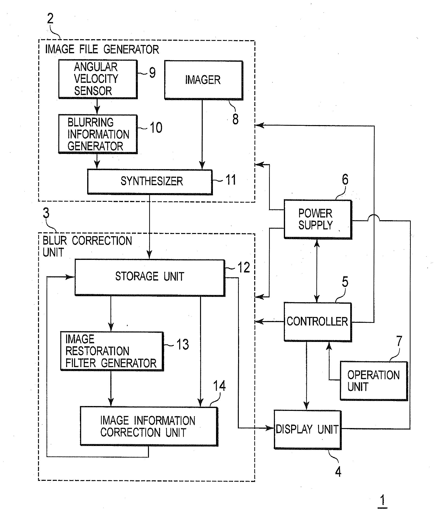
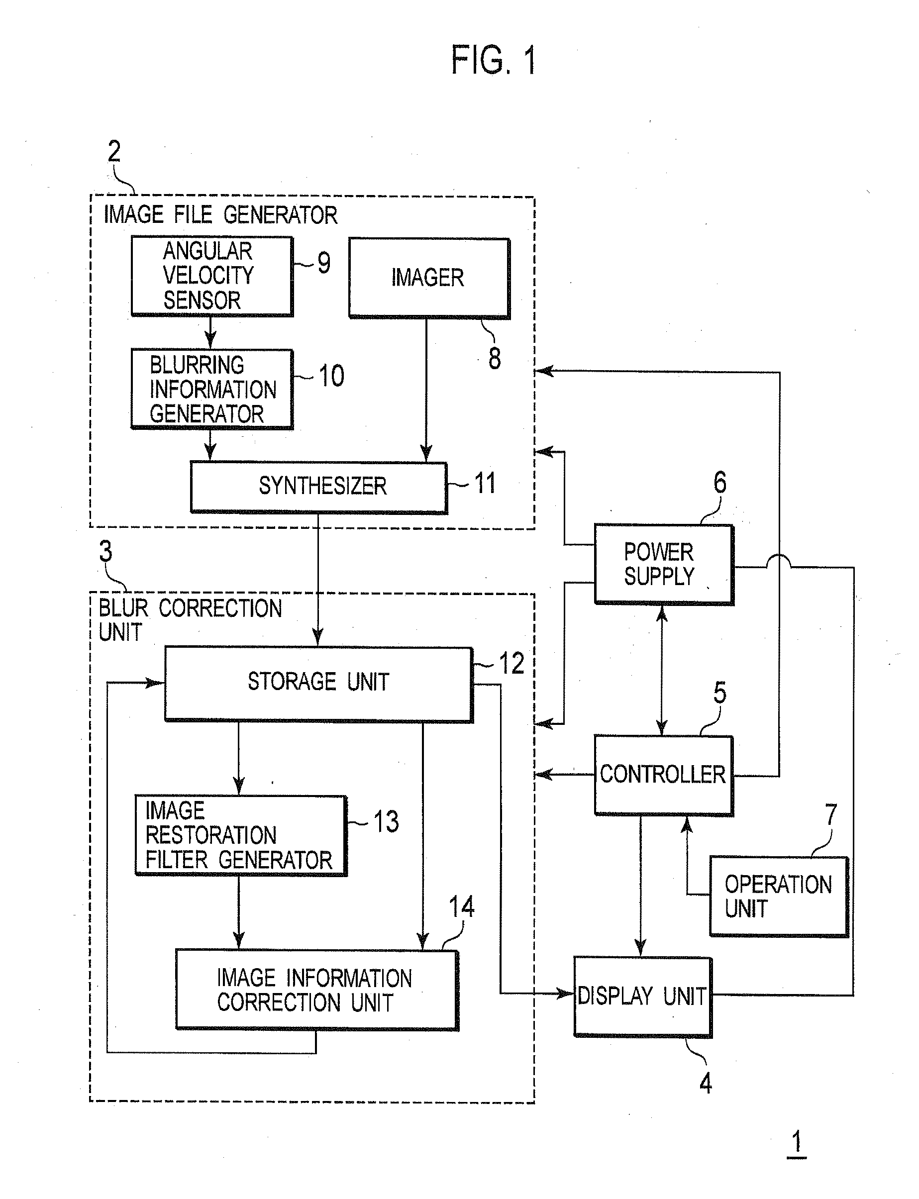
[0105]In following Example 1, firstly, the electronic apparatus including the blur correction device is explained as an image pickup apparatus including an imager as shown in FIG. 1. This electronic apparatus includes a battery and operates by receiving power supply from the battery unless particularly stated otherwise.

[0106]In following Example 1, the blur correction method in the blur correction employs the foregoing image restoration-based correction method, and allows image information pieces of image files to be corrected collectively. In ...

example 2

[0227]In foregoing Example 1, the correction processing can be speeded up by performing the collective image information correction while rearranging image files according to the blurring amount, and by using the motion vector, the PSF or the image restoration filter as the blurring information piece. However, the correction operation can be further speeded up by employing a configuration like Example 2 described below.

[0228]With reference to FIGS. 22A and 22B, descriptions will be provided for a configuration and operations of a blur correction device in Example 2. FIG. 22A is a block diagram showing the configuration of the blur correction device, and corresponds to FIG. 9A for Example 1. FIG. 22B is a conceptual diagram schematically showing timings in the correction operations in the blur correction device in Example 2, and corresponds to FIG. 9B for Example 1. In FIG. 22A, the same reference numerals are given to the same components as those in FIG. 9A, and the detailed descrip...


PUM


Abstract

Image files are rearranged according to the blurring amount obtained from each of blurring information pieces of the image files and displayed as thumbnail images. After several image files are selected from the displayed image files, the image information pieces of the selected image files are sequentially corrected.

Description

[0001]Applicant claims, under 35 U.S.C. sctn. 119, the benefit of priority of the filing date of Apr. 20, 2007, of a Japanese Patent Application No. P 2007-112209, filed on the aforementioned date, the entire contents of which are incorporated herein by reference.BACKGROUND OF THE INVENTION[0002]1. Field of the Invention[0003]The present invention relates to a blur correction device installed in an electronic apparatus typified by an image pickup apparatus such as a digital camera and an image output apparatus such as a display and a printer, a blur correction method thereof, and an electronic apparatus including the blur correction device. Moreover, the present invention also relates to an image file used in the electronic apparatus and an image file creating apparatus configured to create such an image file.[0004]2. Description of the Related Art[0005]Image information piece created with an image pickup apparatus such as a digital camera sometimes suffers from image degradation du...

Claims


Application Information

Patent Timeline
Patent Type & Authority Applications(United States)
IPC IPC(8): H04N5/228H04N5/232H04N5/76
CPCH04N5/23248H04N5/23258H04N5/23264G06T5/003G06T5/20G06T2207/20201H04N23/682H04N23/68H04N23/6812
Inventor HATANAKA, HARUO
Owner XACTI CORP
Why Eureka
Try Eureka