
Method and system for optimized reference signal downlink transmission in a wireless communication system

a wireless communication system and reference signal technology, applied in the field of downlink transmission of reference signals in the network, can solve problems such as performance degradation, and achieve the effect of reducing mai and reducing mai

Active Publication Date: 2008-10-23
SNAPTRACK
View PDF13 Cites 167 Cited by
  • Summary
  • Abstract
  • Description
  • Claims
  • Application Information

AI Technical Summary

Benefits of technology

[0009]In one implementation, the reference symbols can be transmitted by each Node-B in a predefined pattern of subframe locations, with the pattern being selected from a set of unique patterns. Each pattern has a different number of subframes containing the reference symbols. In response to a change in the number of 4-TX capable terminals in the Node-B's cell, the Node-B increases or decreases the number of subframes in which the reference symbols are transmitted by selecting the appropriate one of the unique patterns in the set. The Node-Bs may use the same set of patterns. Alternatively, each Node-B may use a set different from the sets of other Node-Bs, particularly adjacent Node-Bs whose cells may overlap, to reduce MAI.
[0010]The method and system also allows a Node-B to change the location of the subframes in which the reference symbols are transmitted if an adjacent Node-B is causing MAI in the selected subframes. The terminals use the downlink reference symbols to measure interference, in the form of a signal-to-interference (SIR) value, and transmit the SIR value in the uplink to the Node-B. In response to the SIR values, the Node-B may select a different subframe or subframes in which to transmit the reference symbols to thereby reduce MAI.

Problems solved by technology

Also, the transmission by adjacent Node-Bs of the DLRS may cause multiple access interference (MAI) which will degrade performance.

Method used


Image

  • Method and system for optimized reference signal downlink transmission in a wireless communication system
  • Method and system for optimized reference signal downlink transmission in a wireless communication system
  • Method and system for optimized reference signal downlink transmission in a wireless communication system

Examples


Embodiment Construction

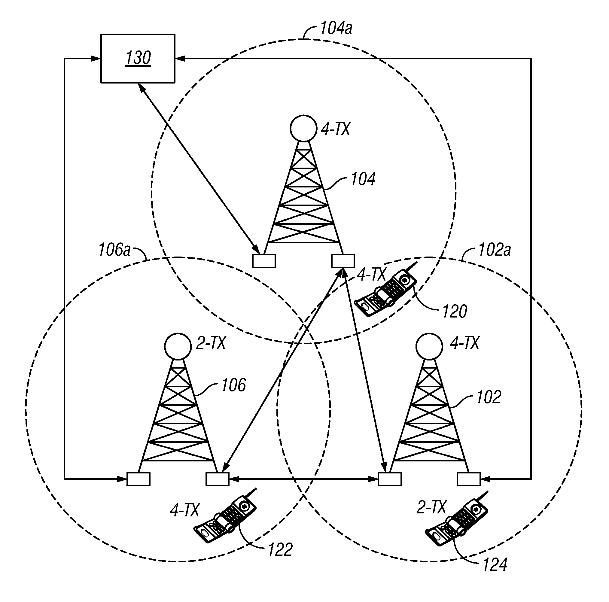
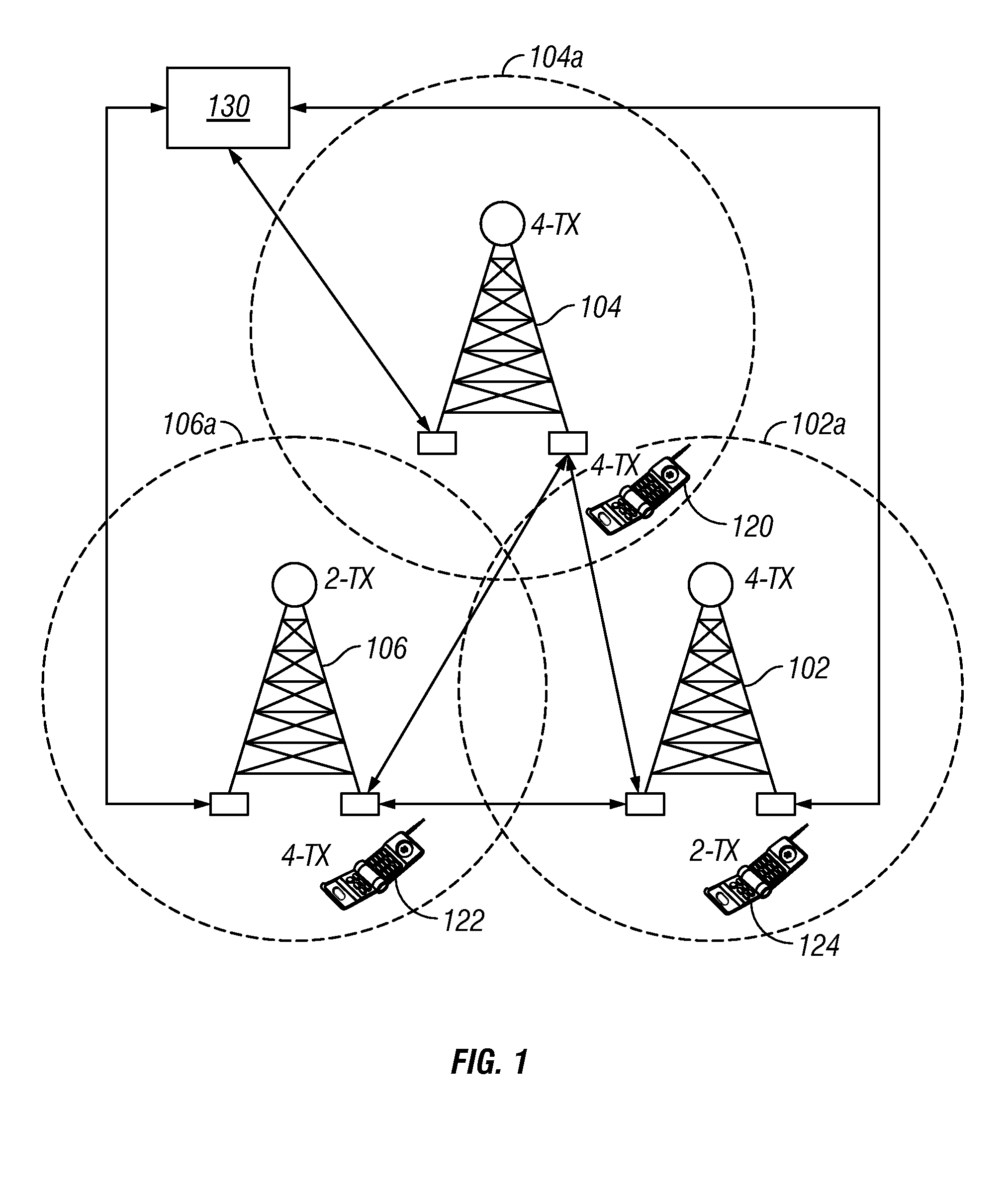
[0025]FIG. 1 is a diagram of a wireless communication system like that proposed by 3GPP LTE. The system includes a plurality of Node-Bs (base stations) 102, 104, 106; a plurality of UEs (mobile phones or terminals), such as mobile phones or terminals 120, 122, 124; and a central gateway 130 that provides connection of the system to the public telephone network. The Node-Bs 102, 104, 106 are connected to the gateway 130 and may be connected to each other.

[0026]Each Node-B may serve one or more cells. In the example of FIG. 1, Node-B 102 serves cells 102a; Node-B 104 serves cells 104a; and Node-B 106 serves cells 106a. 3GPP LTE proposes a multiple-input multiple-output (MIMO) system, so some of the Node-Bs may have multiple receive antennas and some may have multiple transmit antennas. There are no restrictions on the combinations of Node-B transmit and receive antennas. In a typical 3GPP LTE proposed network, a Node-B may have either two physical transmit antennas (2-TX) or four phys...


PUM


Abstract

A method and system optimizes the transmission of a downlink reference signal (DLRS) in a wireless communication system that uses orthogonal division multiple access (OFDMA) for the downlink. Each Node-B (base station) is capable of transmitting the DLRS reference symbols in different subframes of the OFDM radio frame and changing both the number and location of the subframes in response to changing network conditions. The network conditions include the number of terminals being served by the Node-B and multiple access interference (MAI) from adjacent Node-Bs.

Description

BACKGROUND OF THE INVENTION[0001]1. Field of the Invention[0002]The invention relates generally to a wireless communication system, like a cellular network, and more particularly to downlink transmission of a reference signal in the network.[0003]2. Description of the Related Art[0004]A cellular network is a wireless communication system made up of a number of cells, each served by a fixed transmitter, known as a cell site or base station. Each cell site in the network typically overlaps other cell sites. The most common form of cellular network is a mobile phone (cell phone) system. All of the base stations are connected to cellular telephone exchanges or “switches”, which in turn connect to the public telephone network or another switch of the cellular company.[0005]The 3rd Generation Partnership Project (3GPP) is a worldwide consortium to create a specification for a globally applicable third generation (3G) mobile phone system. 3GPP's plans are currently in development under the...

Claims


Application Information

Patent Timeline
IPC IPC(8): H04L1/02H04J99/00
CPCH04L5/0053H04L5/0066
Inventor IMAMURA, KIMIHIKO
Owner SNAPTRACK
Learn More