
Flexible Catheter System

a flexible, catheter technology, applied in the field of catheter systems, can solve the problems of unpredictable movement of implants following release from the delivery system, adverse and unpredictability to the position of the device, and special challenges of occluders

Active Publication Date: 2008-10-23
WL GORE & ASSOC INC
View PDF4 Cites 31 Cited by
  • Summary
  • Abstract
  • Description
  • Claims
  • Application Information

AI Technical Summary

Benefits of technology

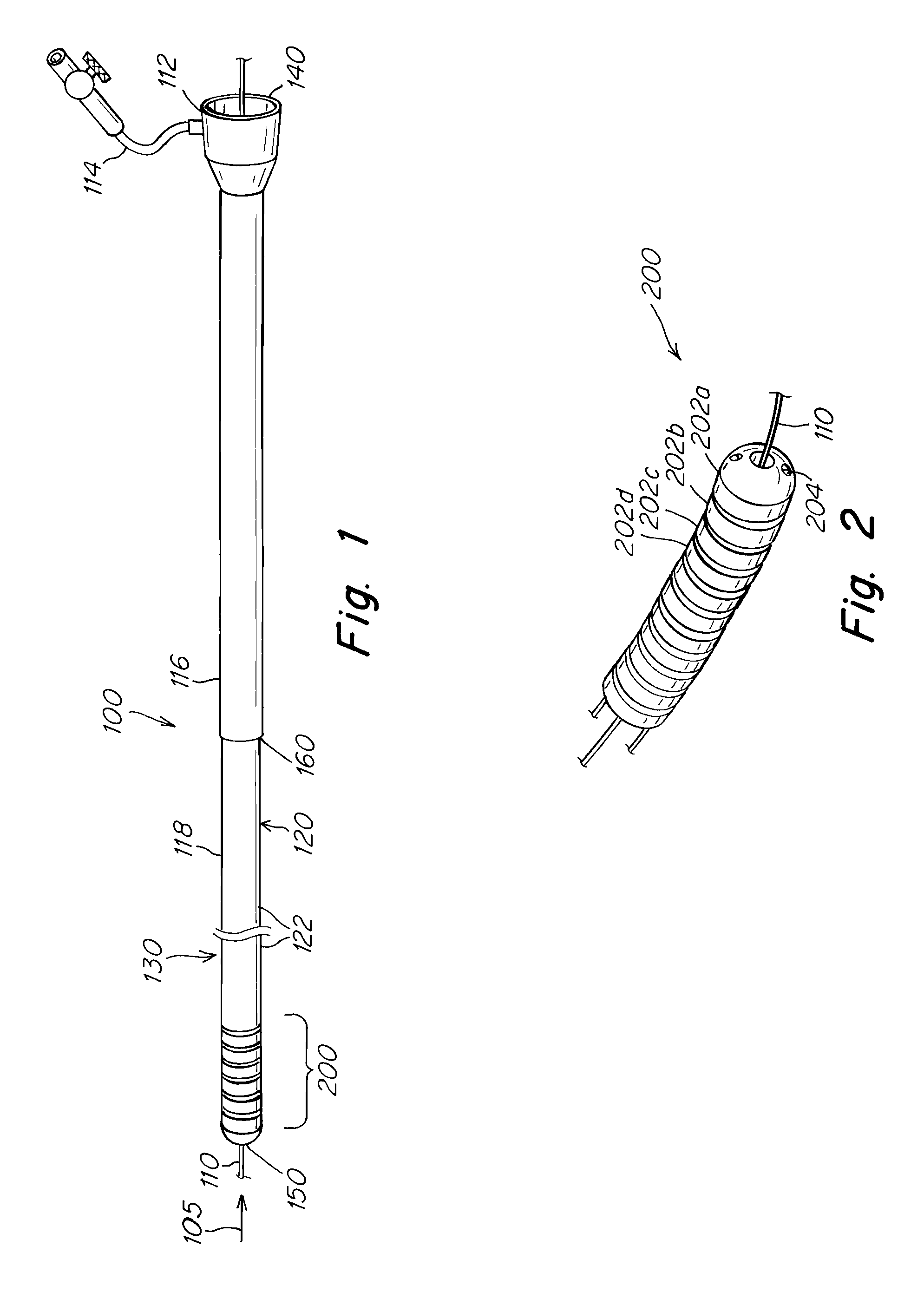
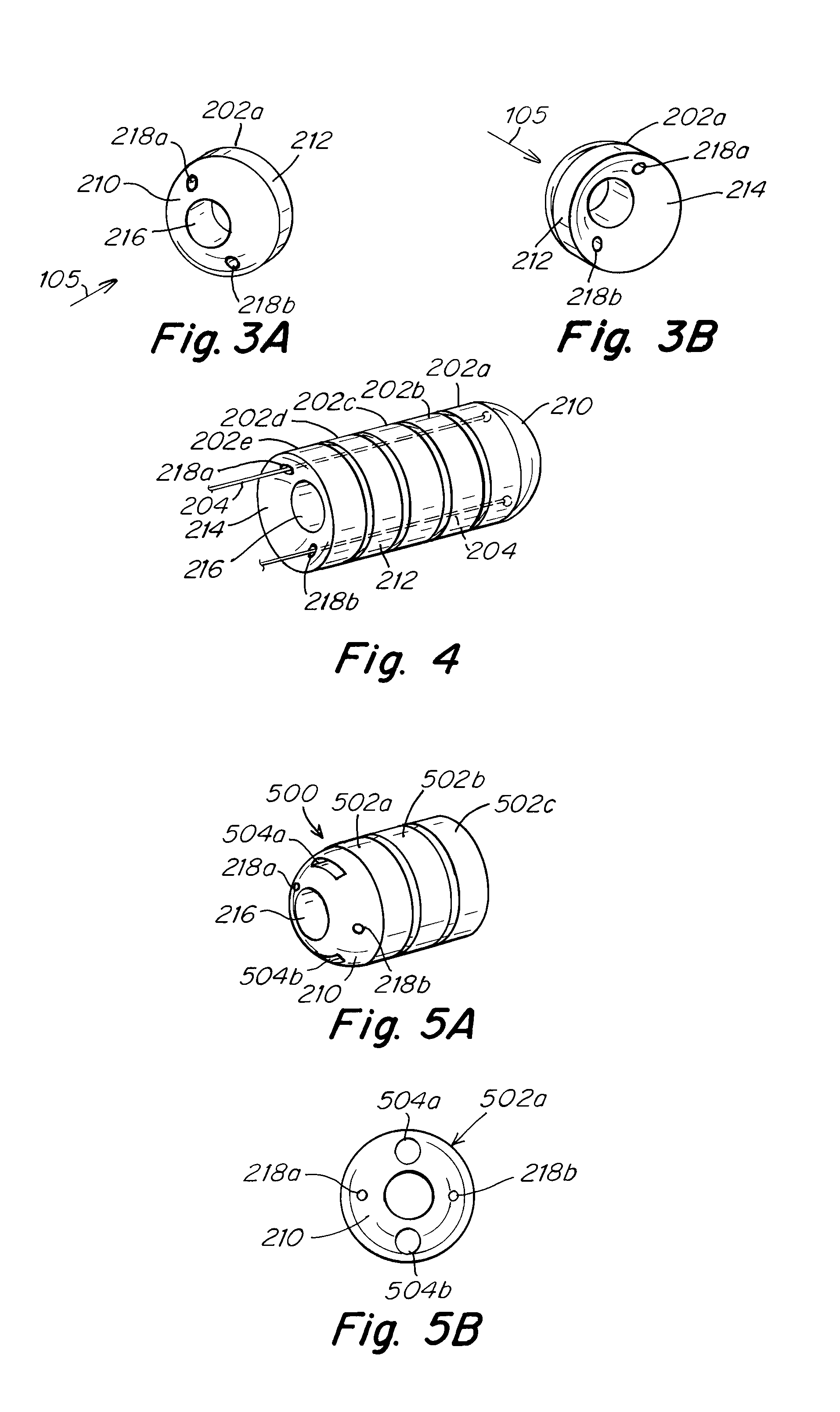
[0015]In certain embodiments, a method includes forming a conduit for insertion into a vasculature of a living body. The conduit includes a plurality of adjacent segments. Each of the plurality of segments has a front face, a back face, and a central axis. The front faces of the segments are adjacent to the back faces of adjacent segments and form a flexible joint between the adjacent segments and enable the segments to be deflected from a configuration wherein the central axes of the segments are aligned. The conduit also includes a main lumen defined by the plurality of adjacent segments. The main lumen passes through the front and back faces of the segments. The conduit further includes a first side lumen defined by the plurality of adjacent segments. The first side lumen is disposed within the segments at a location radially distant from the central axes of the segments. The method also includes disposing a first wire in the first side lumen. The first wire is joined to a most distal segment of the plurality of segments. The first wire is for selectively applying a force to the most distal segment to cause the plurality of segments to be deflected from a configuration wherein the central axes of the segments are aligned.

Problems solved by technology

Among these devices, intracardiac occluders present special challenges for a delivery system.
A common problem with many of these percutaneous delivery systems is that they can often adversely and unpredictably affect the position of the device upon deployment.
Additionally, the movement of the implant that occurs following release from its delivery system can be unpredictable.
Thus, the resulting improper positioning of such an implant can lead to unfavorable outcomes, such as a residual leak in the case of intracardiac occluders, or, in some extreme case, embolization of the implant.

Method used


Image

  • Flexible Catheter System
  • Flexible Catheter System
  • Flexible Catheter System

Examples


Embodiment Construction

[0027]Embodiments of the invention are directed to aspects of a catheter system for delivering, and optionally, retrieving, medical devices within the body through the vasculature (e.g., medical implants, drug release devices, diagnostic devices, etc.). Embodiments of the invention have particular utility for delivering, or retrieving, medical implants in the heart. Embodiments of the invention may be used, for example, to deliver septal occluders used to occlude anatomical apertures, such as atrial septal defects (ASD), ventricular septal defects (VSD) or patent foramen ovale (PFO). In this application, “distal” refers to the direction away from a sheath insertion location and “proximal” refers to the direction nearer the insertion location.

[0028]Referring to the drawings, wherein like reference numerals designate identical or corresponding parts throughout several views, and specifically to FIG. 1, a delivery system 100 is illustrated, including a sheath 116, having a lumen extend...


PUM


Abstract

A percutaneous delivery system with a high degree of flexibility is provided. In one embodiment, the system includes a catheter having a portion comprising multiple segments, linked in series by at least one connecting wire. Joints between the multiple segments provide a high degree of flexibility. In some embodiments, only a distal portion is made up of segments. In other embodiments, the whole length of the catheter is made up of segments. Manipulation of the at least one connecting wire enables manipulation of the segments to flex a portion of the catheter. In one aspect, the invention provides a delivery system that reduces the impact of the delivery system on the final release position of the implant delivered. The delivery system can be used to deploy and / or retrieve implantable medical devices, for example, patent foramen ovale (PFO) occluder.

Description

CROSS-REFERENCE TO RELATED APPLICATIONS[0001]This application claims under 35 U.S.C. §119(e) priority to and the benefit from U.S. Provisional Patent Application No. 60 / 923,985, filed on Apr. 18, 2007, entitled “Flexible Catheter System”, the disclosure of which is incorporated in its entirety by reference herein.BACKGROUND OF THE INVENTION[0002]1. Field of the Invention[0003]The invention relates to catheter systems for delivery and / or retrieval of medical devices.[0004]2. Description of Related Art[0005]In many minimally invasive medical procedures, an introducer sheath or catheter is inserted in a blood vessel to gain access to a site within a patient's body for a diagnostic or therapeutic procedure, and used to deliver medical devices, including medical implants. Medical technology has produced a number of medical devices which are designed to be compressed into a first configuration, such as through a small diameter tube or catheter, in order to facilitate introduction through ...

Claims


Application Information

Patent Timeline
IPC IPC(8): A61M31/00
CPCA61M25/0071A61M25/0138A61M25/0147A61M25/0662A61M2025/015
Inventor CAHILL, RYAN
Owner WL GORE & ASSOC INC
Learn More